Vectronics VEC-1680K User Manual
Page 9
VEC-1680K Owner’s Manual
Vacuum Tube Preamp
9
! ! Install a 390K at R3 and solder.
! ! Install a 390K at R4 and solder.
Locate two (2) 1 Megohm ¼ watts resistors (brown-black-green).
! ! Install a 1 Megohm at R2 and solder.
! ! Install a 1 Megohm at R6 and solder.
This concludes installation of the 11 fixed-value resistors provided in your kit.
Double-check for placement, making sure each value is installed where it
belongs. The two 500K variable resistors (potentiometers) will be installed later
on.
Next, install the kit's capacitors.
! ! Find the .01 uF, 100 volt, disc ceramic capacitor (.01 or 103). Install at
C7 and solder.
Locate two (2) .1 uF, 500 volt, disc ceramic capacitors (.1 or 104).
! ! Install a .1 uF at C10 and solder.
! ! Install a .1 uF at C11 and solder.
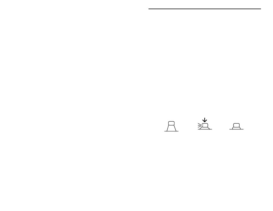
Locate the two (2) .22 uF multilayer capacitors. Avoid using force or excessive
heat when installing these. If the lead spacing isn't right, pre-form leads to the
correct spacing before inserting into the PC board.
Incorrect
Ooops!
Correct
! ! Install a .22 uF at C3 and solder.
! ! Install a .22 uF at C9 and solder.
The remaining capacitors in your kit are electrolytic. Electrolytic caps are
polarized and must be installed the correct way in order to work. Each
capacitor's plus (+) mounting hole is marked on both the circuit board and parts
placement diagram. If the markings on the capacitor body are unclear, the plus
(+) lead is always the longer of the two.