Xilica XD Series User Manual
Page 2
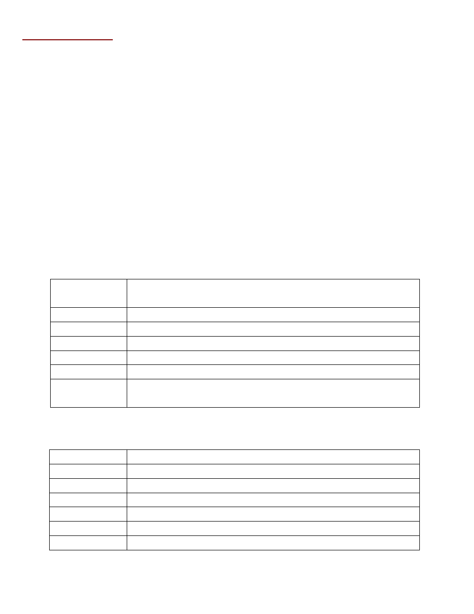
PROTOCOL STRING
<01><READ/WRITE><SENDER>
<HEADER><VALUE>...<PROCESS>
<CHECKSUM><02>
1 1 1 1 Varies 1 1 1 <= size in bytes
<READ/WRITE>
-
Read = ‘R’ or <52>, Write = ‘W’ or <57>
<SENDER>
-
Device number of the sender: <7F> is normally used.
The bytes in RED can be inserted many times inside a single Protocol String. There is no limit in the number of
<HEADER><VALUE> combo as long as the whole block (from <01> to <02>) is less than 256 bytes. When a
<HEADER><VALUE> is received, the corresponding new parameters are stored in the memory. However, it is
processed only when a <PROCESS> (<1F>) is received. The <PROCESS> can be inserted more than once if multiple
actions are desired, eg. Mute multiple channels at the same time.
<HEADER>
The <HEADER> is used to identify the types of value following the header.
Command Header <03 to 07>; <03> = 4 bytes <VALUE>… <07> = 8 bytes <VALUE>
Command ID in ASCII character
Device Header
<08> Device # where this command is sent to
I/O Header
<09> Input / Output section of the device
Channel Header
<0A> Channel #
Aux Header
<0B> For extra information such as EQ Num, FBX Num ,etc
Column Header
<0C> Used in Special Commands like Level Increment
Data Header
<10 to 18>; <10> = 1 byte <VALUE> … <18> = 9 bytes <VALUE>
The parameter data value to be changed
<VALUE>
<VALUE> must always follow the <HEADER>.
Command Value
For the commands, related table in this document
Device Value
<20> for Device 0... <2F> for Device 15
I/O Value
<20> for Input, <21> for Output
Channel Value
<20> for Channel 0... <27> for Channel 7
Aux Value
<20> for Aux # 0... <1F> for Aux #31
Column Value
Used in Special Commands, see related table in this document
Data Value
For the list of Data values, see related table in this document
Note: For Data values > <60> (96 in decimal), convert the data into a Base 96 number. Add <20> to each digit to get
the Hex bytes. This restricts all Data value hex bytes between <20> and <7F>.