3 rear panel m130/m131 – AMETEK DLM600 Series User Manual
Page 6
Sorensen DLM600 Series
M6 Option: M9G, M130, M131
Addendum
3
2.1.3 Rear Panel M130/M131
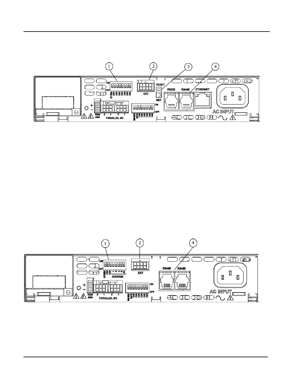
Figure 2.1-1 and Figure 2.1-2 label the pertinent rear panel components for the typical
M130 and M131 Ethernet option.
Figure 2.1-1 Typical Rear Panel of M130 Ethernet Option
1 – Configuration Switch
2 – External User Control Signal Connector
3 – (Not in M131) RESET switch and green dual-purpose NET LED
RESET switch: returns configuration parameters to factory default (must be
depressed until NET LED blinks at least twice).
NET LED: when solid-lit, indicates Network Connectivity; blinking indicates
Instrument ID. If the LED is off, there is no Ethernet connection found by the
power supply.
4 – Connections for Ethernet (RJ-45) with built-in 10/100 indicator (on right top of the
RJ45 connector) and an Activity indicator (on the left top). Also RJ-11 connectors
for RS232 and RS485. (No RJ-45 connector on M131).
Figure 2.1-2 Typical Rear Panel of M131 Ethernet Option