AMETEK ReFlex Quick Reference guide User Manual
AMETEK Equipment
QUICK REFERENCE GUIDE: REFLEX POWER™ NETWORK COMMUNICATION AND OUTPUT CONNECTIONS
The ReFlex Power™ system is designed to run single or multiple power supplies
and/or loads through one Controller module; the system is operated by computer
with an Ethernet connection. This quick reference guide provides brief
instructions for connections and communication startup. For full connections
information and programming information, please refer to the ReFlex Power™
manuals and technical notes referenced at the end of this guide.
O
VERVIEW
This Quick Reference Guide assumes that, with all power disabled, you have
assembled your ReFlex Power system and main power connections per the
ReFlex Power Operation Manual (Part Number M380056-01) on the CD
provided with your system. This guide provides instructions to first, enable all
modules to output voltage by connecting their discrete signals. Next, connect
the control computer to the ReFlex Power™ system; power on the system; then
launch the Ethernet communication program and find/set the IP and Port
addresses, and run/control the ReFlex Power™ system via SCPI commands.
E
NABLING
O
UTPUT
Disable the Remote Inhibit of the Controller module and enable the outputs of
each power and/or load module with a jumper plug to as follows:
• For the ReFlex Power™ Controller module, connect Pins 1 and 9 on the
front panel interface connector, using either Loop-back Connector Assembly
5380509-01 or Cable Assembly 5380441-01 or -03.
• For all other ReFlex Power™ modules, connect Pins 1 and 6 on the front
panel interface connector, using either Loop-back Connector Assembly
5380508-01 or Cable Assembly 5380443-01 or -03.
Refer to Mating Connector Technical Notes for additional information.
C
ONNECTING THE
C
ONTROL
C
OMPUTER TO THE
R
E
F
LEX
P
OWER
™
S
YSTEM
Connection requires RJ45-type connectors with Category 5 or 5e, (Cat 5)
cables; two straight through for Network connection or one crossover for direct
connection.
Figure 1. Ethernet Network Connection
Network Connection
Using two straight through cables, connect the control computer and the Controller from their
respective Net/LAN connectors, to either a local switch or hub (Figure 1).
Figure 2. Ethernet Direct Connection
Direct Connection
If the control computer’s Ethernet interface does not support Auto-MDIX, then
use a crossover cable to connect the control computer directly to the Controller
from their respective Net/LAN connectors (Figure 2). Using a cross-over cable
may require changing your computer settings to establish communications
(explained in “Launching Ethernet Communication” in this guide).
P
OWERING ON THE
S
YSTEM
Toggle the Power switch on the Controller’s front panel to power on the ReFlex
Power™ system. Once the system completes its power-on cycle, the Controller
indicators normally illuminate as follows:
Power = on; Fault = off; and Bus = blinking on and off at this stage.
After power-on and Ethernet connections are made, the Controller LAN indicators illuminate
as follows: Net = on; LAN = on; Com = on during network traffic but otherwise it is off.
L
AUNCHING
E
THERNET
C
OMMUNICATION
Since the ReFlex Power™ Controller is
™ (LAN eXtensions for
Instrumentation) class C compliant, its Ethernet interface default is DHCP and
Auto-IP enabled. Execute the LXI_Browser_setup.exe file supplied on the ReFlex
Power™ CD-ROM (P/N M380399-01). This installs the LXI Browser tool on
your computer; double-click the LXI™ Browser icon to find and display
(Figure 3) the IP Address of the ReFlex Power™ Controller.
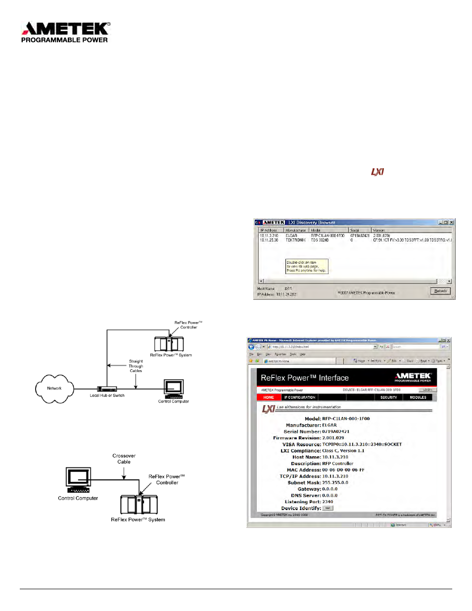
Figure 3. LXI Discover Browser Window
In the LXI™ Discovery Browser window, double-click the Controller IP
Address to initialize the ReFlex Power™ Ethernet interface. The Home Page
displays with the current information for the selected Controller.
Figure 4. ReFlex Power™ Ethernet Interface Home Page
If a DHCP server is not found, an address in the range of 169.254.[1 thru
254].then [0 thru 255] will be selected.
M380056-04 Rev E
1 of 3