AMETEK XG 850 Watt Series Quick Start 1.09 and earlier User Manual
AMETEK Equipment
Part Number M370078-04 Rev D January 2009
© 2007-2009 AMETEK Programmable Power, Inc. All rights reserved.
www.programmablepower.com
Q
UICK
R
EFERENCE
G
UIDE
:
XG 850 Watt Series Programmable DC Power Supply
(firmware v1.09 and below)
The XG is equipped with a rotary Adjust/Enter control to provide a streamlined front panel for faster setup. Set voltage and current quickly and
easily using the rotary Adjust/Enter control and the 9-position Mode control. The information provided in this Quick Reference Guide is for basic
usage of the front panel and for understanding the menu system. See the other side of this Quick Reference Guide for a map of the front panel
menu system. For complete information on the XG, please refer to the XG 850 Watt Series Programmable DC Power Supply Operating Manual
(Part number: M370078-01).
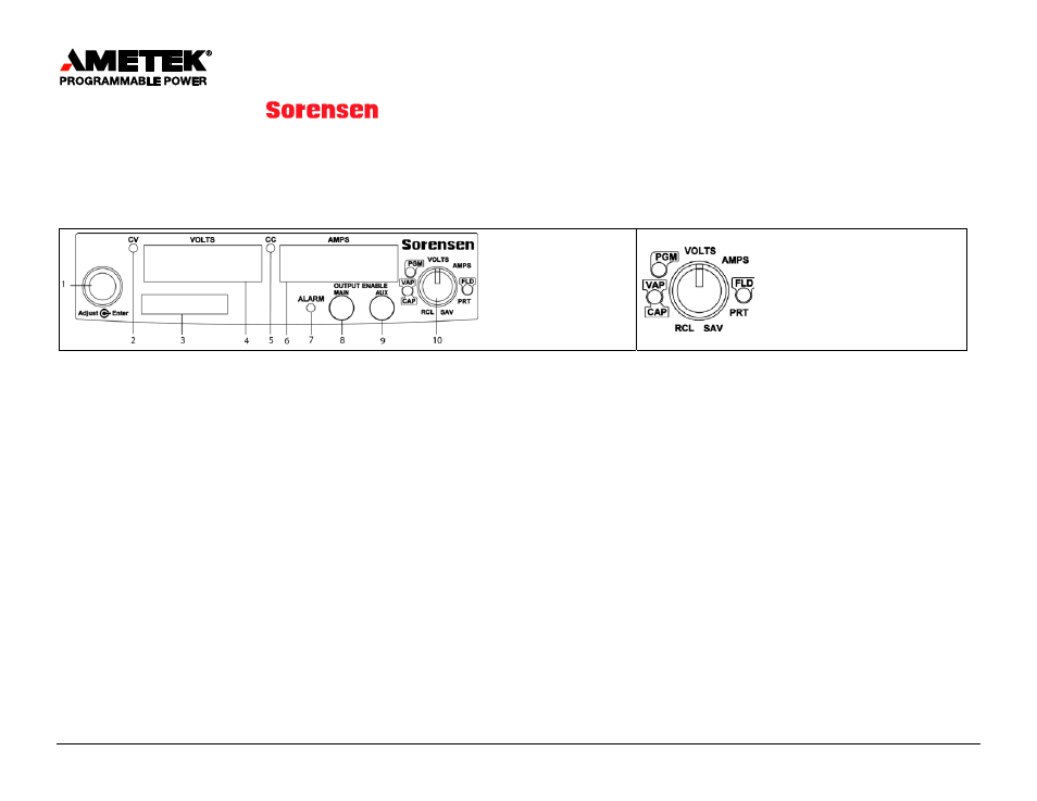
1. Rotary Adjust/Enter Control
2. Constant Voltage Mode LED
3. Model Identification Label
4. Output Voltage Display
5. Constant Current Mode LED
6. Output Current Display
7. Alarm Indicator LED
8. Output On/Off Button
9. AUX On/Off Button
10.l 9-position Mode Control
VOLTS: Voltage Programming
AMPS: Current Programming
FLD: Foldback
PRT: Protection
SAV: Save User Setting Memory Locations
RCL: Recall User Setting Memory Locations
CAP: Current Analog Programming
VAP: Voltage Analog Programming
PGM: Programming
XG Front Panel Controls, Displays, and Indicators XG
Rotary
Adjust/Enter Control
General Procedures for Setting Up Features
•
To select a mode, rotate the 9-position Mode control to the desired mode.
•
To select the feature or setting, turn the rotary Adjust/Enter control to scroll through the different available settings of that mode.
•
The settings appear on the output display.
•
Press the rotary Adjust/Enter control to select the feature or setting.
•
Set each value using the rotary Adjust/Enter control. When the value has been selected, press the Adjust/Enter control to commit the
updated value.
Setting the Output Voltage and Current Limit Using Tracking Mode
To access the tracking mode where new values take effect as the rotary Adjust/Enter control is turned:
1. Select VOLTS or AMPS on the 9-position Mode control. The set point will blink and the unit will be in coarse tracking mode.
•
When VOLTS mode is selected, the voltage set point will blink in the output voltage display.
•
When AMPS mode is selected, the current set point will blink in the output current display.
2. Use the rotary Adjust/Enter control to adjust the set point.
3. Press the Adjust/Enter control to use fine adjust tracking mode. The set point blinks faster when the unit is in fine tracking mode.
4. Use the rotary Adjust/Enter control to fine tune the set point.
5.
Once the set point has been selected, press the Adjust/Enter control to exit tracking.