Artel DLC410 User Manual
Digilink, Dvb-asi and sd-sdi video-over-ip gateway [dlc410, Quick start guide
Simplifying Media Transport
™
DigiLink
Media Transport Simplified
QUICK START GUIDE
DVB-ASI and SD-SDI Video-Over-IP Gateway
[DLC410]
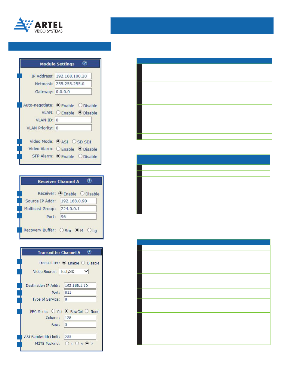
CHANNEL A (OR B) RECEIVE Configuration
Configures settings for data received from DLC410 IP network
1
RECEIVER: Enable Channels to RECEIVE video from network
2
Source IP Address of DLC410 or SMPTE 2022 based Ethernet transmitter
3
IP MULTICAST GROUP Address
Special multicast address DLC410 receives traffic from during multicast reception
4
TC/IP PORT Address
Logical TCP port address that DLC410 receives traffic on
5
RECOVERY BUFFER
1
Size to handle late arriving and misordered
packets (see DLC410 manual for more info)
• Large setting provides greater ability to receive late and misordered packets
• Recovery Buffer Size and FEC settings determine DLC410 latency (see manual)
1. In ASI mode, only the small buffer setting should be used to avoid excessive latency
MODULE SETTINGS
1
IP Address of DLC410 Module
• This is the source IP address of all traffic transmitted and the destination IP address of
all traffic received
• Also the address that responds to “Pings”
2
VLAN ENABLE/DISABLE and Configuration
• Specifies whether VLAN tag is populated on outgoing Ethernet frames
• Specifies VLAN ID that is set on outgoing Ethernet frames
• Specifies VLAN priority (1 through 7; 1=low, 7=high)
• VLAN ID/VLAN priority only display when VLAN Enable selected
3
VIDEO MODE for Channel A and B
Specifies video mode for all channels (ASI or SDI/SDTI)
4
ENABLE ALARM on loss of active video
If enabled, alarm will activate if active video signal is lost
5
ENABLE ALARM ON SFP not present
If enabled, alarm will activate if an SFP is not installed
?
DLC410 Module or Receiver or Transmitter Settings Help
CHANNEL A (or B) TRANSMIT Configuration
1
Enable Channels to TRANSMIT video to network
2
Transmit Video Source
• TRANSMIT video source BNC or other slot
• Selects source of transmit video
• For DL4000, displays backplane slots 1-4
• For DL4360x and DL4300, displays backplane slots 1-4, 5-8, or 9-12
3
Destination IP Address of DLC410 or SMPTE 2022 based Ethernet receiver
4
Logical TCP port address that IP packets are transmitted on. Number must be
between 1 and 65535.
5
Specifies IP Type of Service (TOS) bits for transmit data
Specifies IP priority level to route traffic through network to destination
6
Specifies Forward Error Correction (FEC) settings
• Specify Column or Row/Column or No FEC
• Specify FEC matrix (row and column) size (maximum 1,500)
7
Specifies ASI bandwidth limiting (ASI mode only)
• If transmit ASI traffic exceeds specified bandwidth, traffic will be throttled
• ASI bandwidth limit/M2TS packing displays when ASI mode selected
(module settings)
8
Specifies Number of MPEG frames per IP frame (ASI mode only)
• For lowest latency, choose 1 (least efficient use of bandwidth)
• For most efficient use of bandwidth, choose 7
Transmitter Settings
1
2
3
4
5
6
7
8
Receiver Settings
1
2
3
4
5
Module Settings
1
2
3
4
5