2 amc bay b1, Figure 2-4, Amc module b4 interconnection scheme – Artesyn ATCA-F120 Installation and Use (August 2014) User Manual
Page 39: Hardware preparation and installation
Hardware Preparation and Installation
ATCA-F120 Installation and Use (6806800D06J)
39
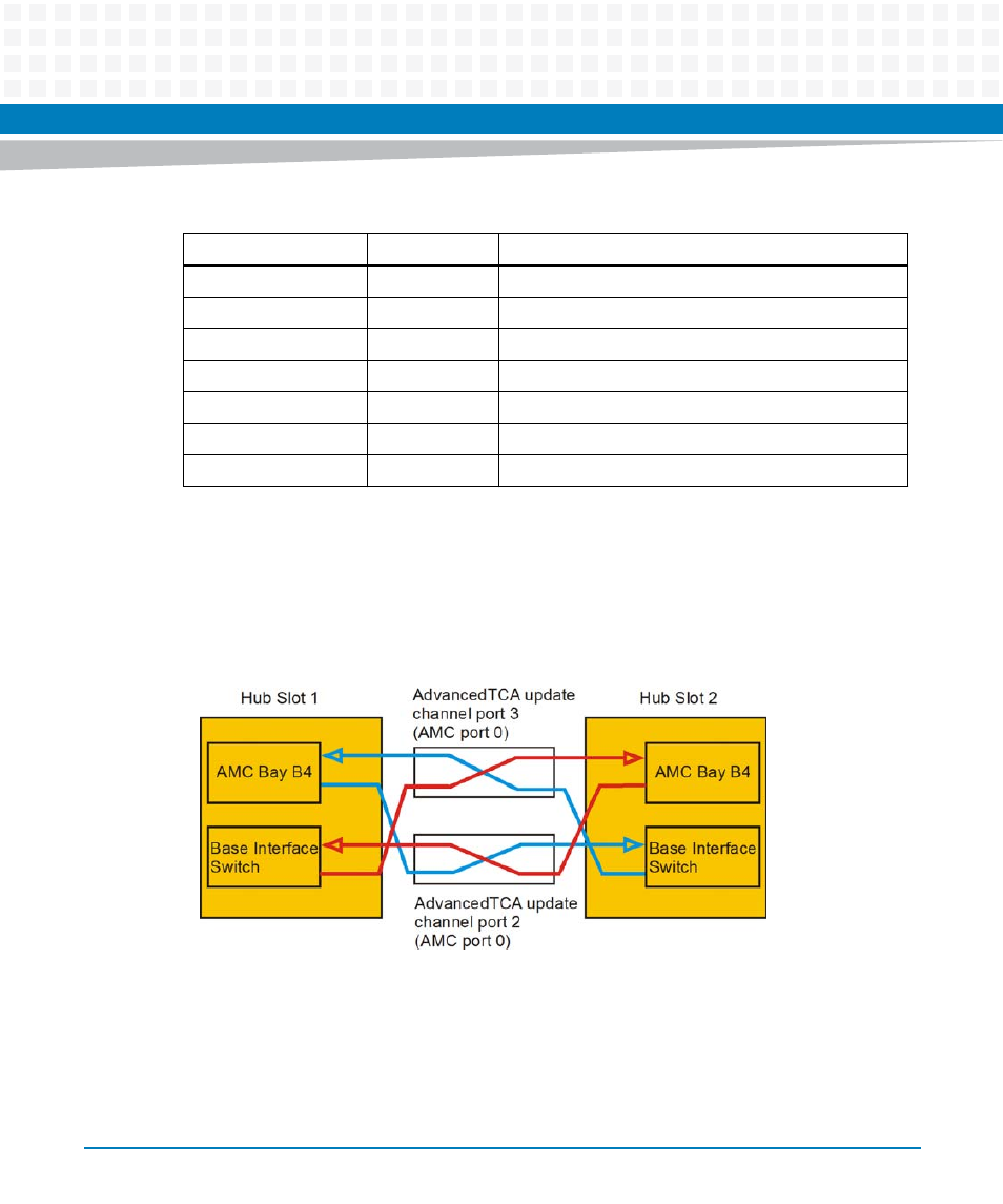
The AMC modules installed in AMC bay B4 of both ATCA-F120 blades in a shelf are
interconnected via the AdvancedTCA update Channel interface (ports 2 and 3) through the
backplane. The following figure illustrates the interconnection scheme. It is applicable to all
Artesyn AdvancedTCA shelves.
2.7.1.2
AMC Bay B1
This AMC bay is designed to support different types of AMC modules. The mechanical design
allows to install single-width AMCs with midsize face plates.
8
Ethernet Dual MAC (Intel 82671EB)
9
Ethernet Dual MAC (Intel 82671EB)
10
Ethernet Dual MAC (Intel 82671EB)
11
Ethernet Dual MAC (Intel 82671EB)
Extended Options
12 - 18
Unused
19
Zone 3 connector P30 row 7 pin pair A-B
20
Unused
Figure 2-4
AMC Module B4 Interconnection Scheme
Table 2-5 AMC Bay B4 - Port Assignments (continued)
Connector Region
AMC Port #
Usage on ATCA-F120