1 connectors, 1 serial interface, Figure 3-3 – Artesyn ATCA-F120 Installation and Use (August 2014) User Manual
Page 50: Location of serial interface connector
Controls, LEDs and Connectors
ATCA-F120 Installation and Use (6806800D06J)
50
3.3.1
Connectors
The blade provides the following connectors at its face plate:
One serial interface
Ethernet management interface
AMC bay B1 Ethernet management interface
Ethernet Base Channel interface
3.3.1.1
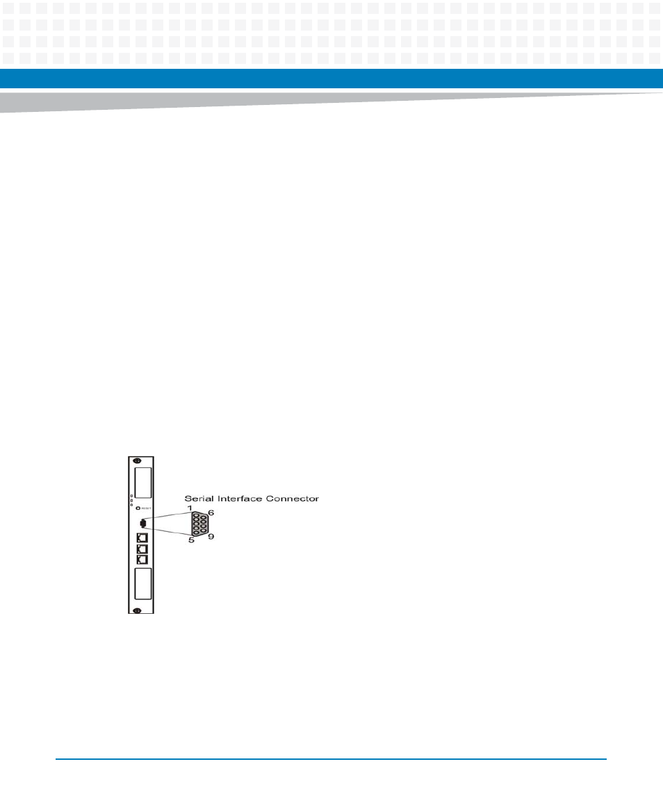
Serial Interface
The serial interface connector allows to establish a serial console connection between the
ATCA-F120 and an external computer, for example a laptop. The serial interface is primarily
intended for management purposes and allows for example to access the blade’s U-Boot
firmware (see
Chapter 5, U-Boot Firmware, on page 87
).
The following figure shows the location of the connector.
This interface is typically used to connect to and configure the U-Boot firmware. Refer to the
chapter "U-Boot Firmware" for further details.
Figure 3-3
Location of Serial Interface Connector