BECKHOFF BK2000 User Manual
Page 13
Basic information
BK2000
13
Special signals and
interface
The BK2000 supports bus terminals with further interfaces such as RS232,
RS485, incremental encoders or others. These signals can be controlled
just like the above-mentioned analog signals. To some extent, a bit width of
16 does not suffice for the special signals. The bus coupler is capable of
supporting any byte width. With regard to accessing these values, please
ensure that data consistency is safeguarded. That is to say, do not send
any "update" command between access operations and do not switch the
bus coupler to "freewheeling" mode.
Default assignment of
inputs and outputs to the
process image
When the bus coupler is first switched on it determines the number of
attached bus terminals and sets up a list of assignments. This list
distinguishes between analog channels and digital channels and between
input and output; which are grouped separately. The assignments begin
immediately to the left of the bus coupler. The software in the bus coupler
creates the assignment list by collecting the entries for the individual
channels one at a time, counting from left to right. These assignments
distinguish four groups:
Function type of the channel
Assignment level
1.
Analog outputs
byte-wise assignment
2.
Digital outputs
bit-wise assignment
3.
Analog inputs
byte-wise assignment
4
Digital inputs
bit-wise assignment
Complex multi-byte signal bus terminals are represented as analog inputs
or outputs
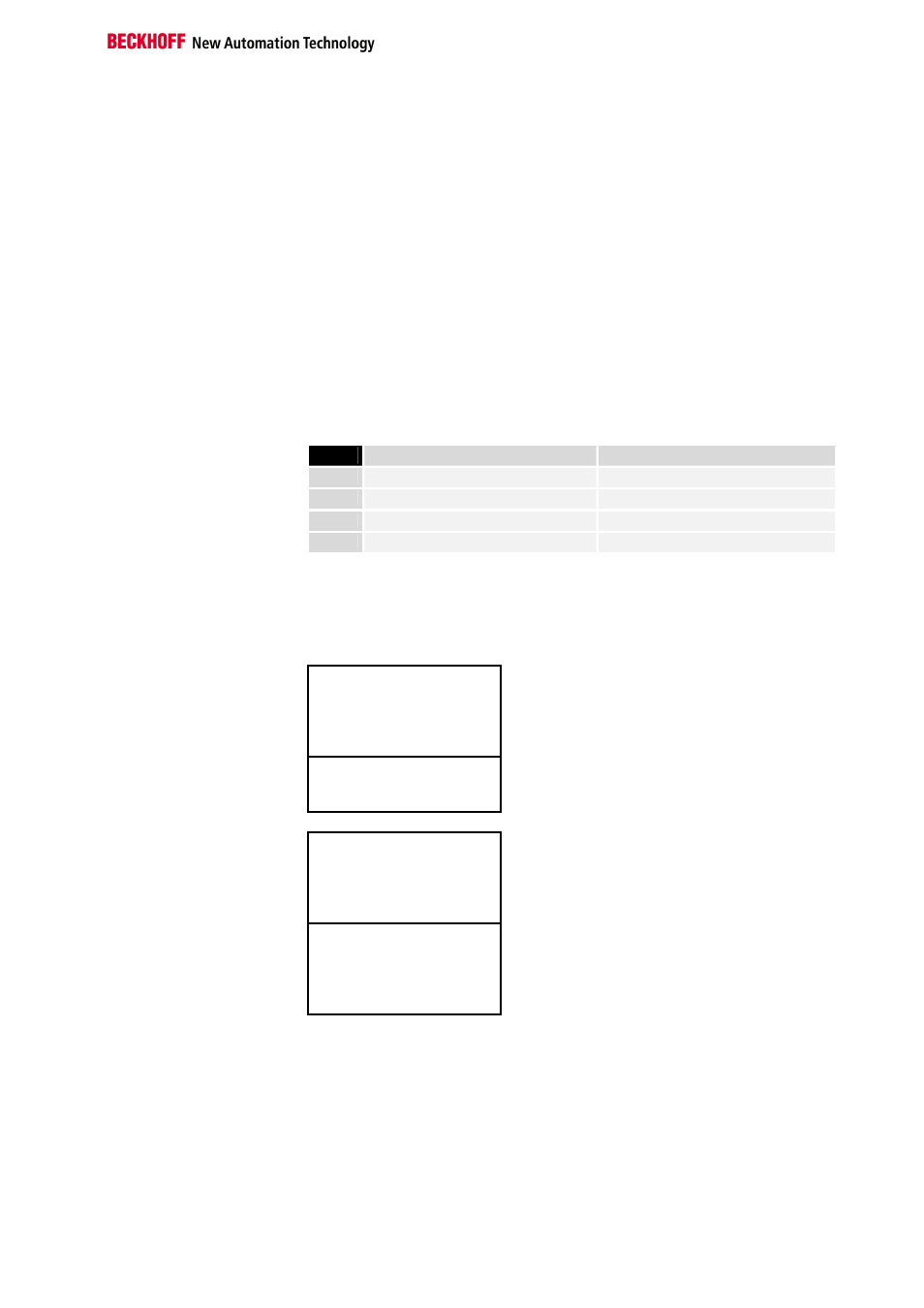
Overview of the subdivision of the process image in the bus coupler:
Output data in the bus
coupler
O0
...
byte-oriented data
...
Ox
Ox+1
bit-oriented data
Ox+y
Input data in the bus
coupler
I0
...
byte-oriented data
...
Ix
Ix+1
...
bit-oriented data
...
Ix+y