BECKHOFF BK2000 User Manual
Page 18
Beckhoff-Lightbus coupler BK2000
18
BK2000
The master interfaces can be subdivided into two fundamental groups, the
PC boards C1200 and C1220 and the PLC boards C1120, C1300, C1400,
C1500 and C1600. The PC boards are configured by PC using the SPS
TwinCAT or S2000 software or using corresponding high-level language
drivers. The PLC boards feature an RS232 interface through which the
configurations can be set using a PC. The configuration package for the
PLC boards is referred to as the S1120.
The telegram structure and
addressing
Data is exchanged between the master and slaves by way of individual
telegrams. The telegrams address the station and simultaneously transport
4 bytes of output data to the slave and 4 bytes of input data from the slave
to the master. One telegram has a run time of 25 µs.
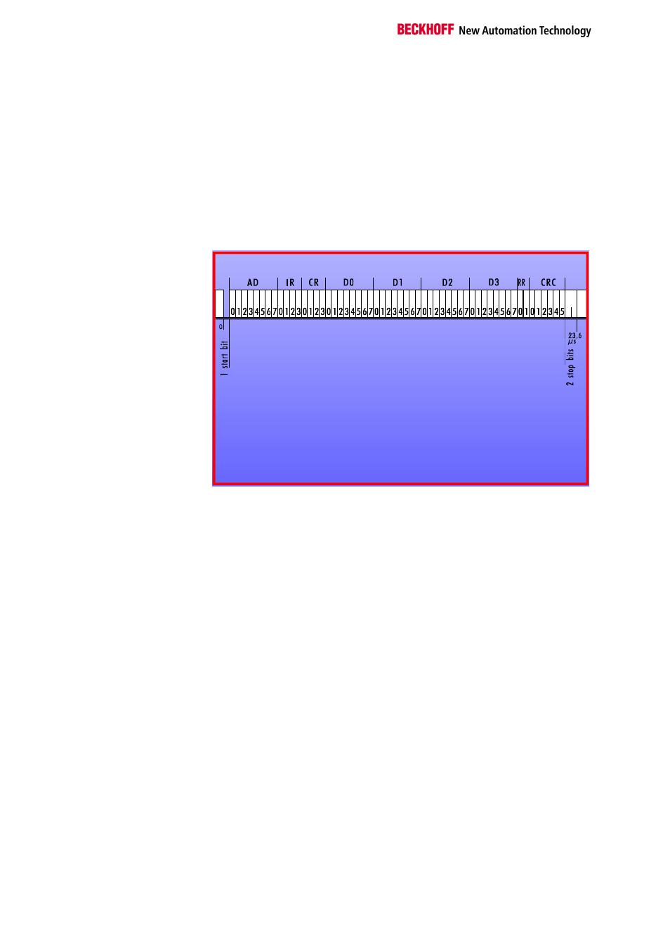
I I / O - L i g h t b u s : t e l e g r a m - l a y o u t
4 control bits to manage the te legra m function
C R 0 - C R 3
C R C 0 - C R C 5
6 bits CRC - checksum
R R 0 - R R 1
2 reserve -Bits
D 0 . 0 - D 0 . 7
8 data bits for input/output
8 data bits for input/output
8 data bits for input/output
8 data bits for input/output
D 3 . 0 - D 3 . 7
D 2 . 0 - D 2 . 7
D 1 . 0 - D 1 . 7
I R 0 - I R 3
4 Interrup t inputs/outputs
for address indep endent signal creation and outp ut
A D 0 - A D 7
8 bit ad ress field (0 - 255)
The controller can access a station between 1 and 255 (via the master) by
way of the address field AD. The address of a station is distributed by the
master during the startup phase in the physical order of the stations on the
ring. The station after the master is assigned the address 1, and all further
stations are assigned a consecutive number. Each station receives a
telegram with the structure described above. The data length is defined as
4 bytes. The master sends a telegram with an address and corresponding
data to a station. The station accepts the data and sends its own data to
the master in the same telegram.
Access to a
bus coupler
The bus coupler is an intelligent slave. Thanks to its processor, it is
capable of offering extensive functions. Use of a bus coupler's functions
requires an extensive exchange of data. A bus coupler is addressed with
the telegrams in the way described above. However, the bus coupler is
capable of processing a far greater number of bytes than only four bytes.
The bus coupler creates an internal process image which, subdivided into
input and output areas, is organized in words in the memory. The first data
byte D0 of the telegram for selection of a memory word is used to address
a word from the memory. The second data byte D1 operates as a control
byte with which it is possible to switch between the "READ" and
"READ/WRITE" modes. With the contents "00", the telegram has a "READ
capability", i.e. input data is written into the bus coupler's memory and the
contents of the input memory with the corresponding address are copied
into the telegrams. The contents 128 (80hex) in the byte D1 initiate a
"READ/WRITE access". The contents of the telegram are copied into the
output memory and the input memory is additionally read and transferred
to the muster.
For access to the bus coupler's memory area, a constant must be
additionally assigned to the control byte of the telegram. The contents
10hex signify that a "Page 0 WRITE access" to the memory is enabled.