Beckhoff-lightbus bus coupler bk2000 – BECKHOFF BK2000 User Manual
Page 6
Basic information
6
BK2000
for separately powered
groups
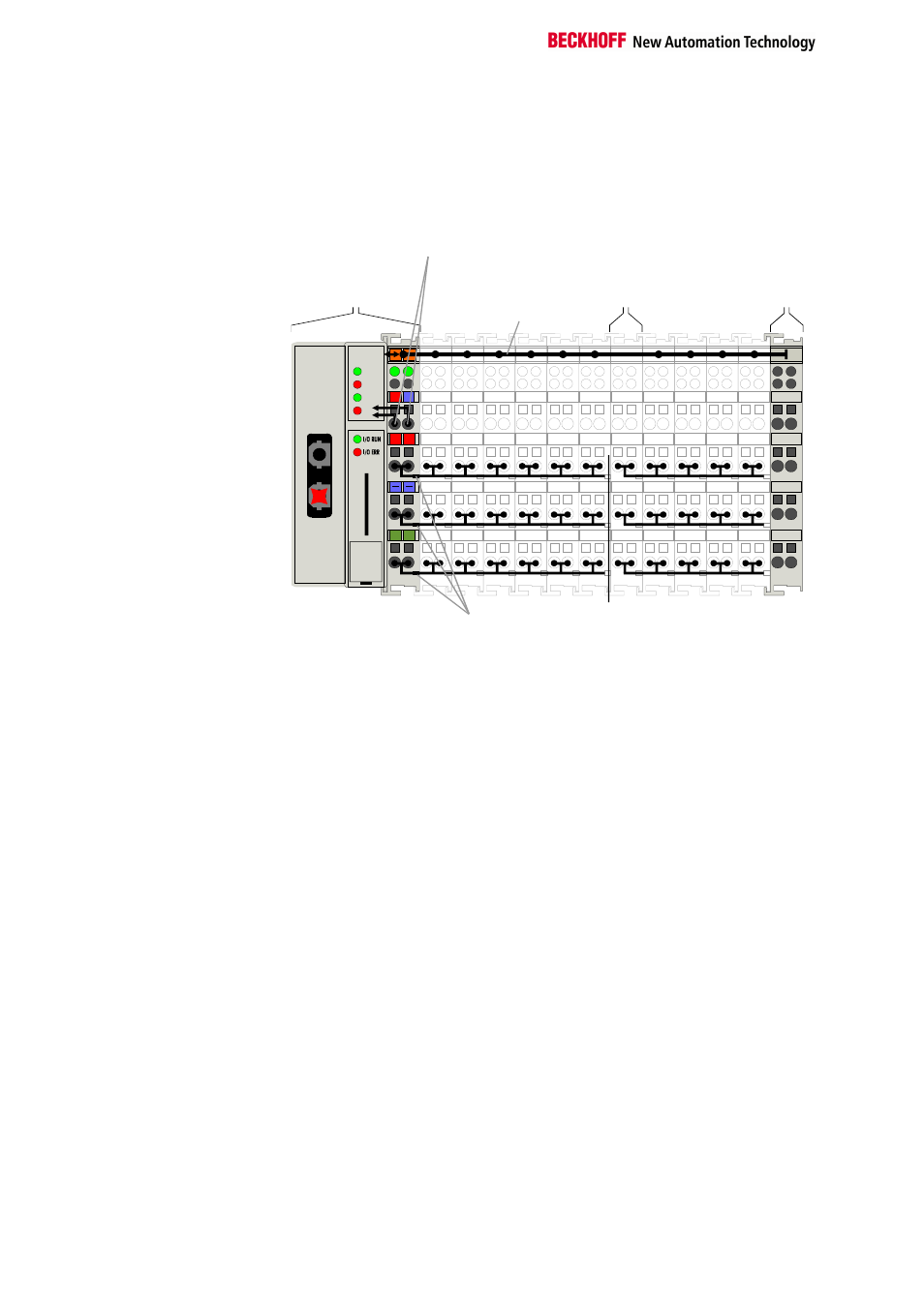
You can use power input terminals to subdivide the terminal row as desired
into groups, each with a separate power supply. These power input
terminals are not taken into account for addressing the terminals, you can
insert them at any position along the terminal row.
You can install up to 64 terminals on a terminal row, including power input
terminals and the end terminal.
The principle of the bus
terminal
02
01
+ +
PE PE
BE
CK
HO
FF
24V
0V
K-Bus
End terminal
Electrical
isolation
Potential
supply
terminal
Power
contacts
Supply voltage
for the
bus coupler
CYC
E R R
W D
II/O -Lightbus
Beckhoff-Lightbus
bus coupler
BK2000
BK
2
00
0
Bus couplers for various
fieldbus systems
You can use a variety of bus couplers to attach the electronic terminal row
quickly and easily to the various fieldbus systems, and you can also sub-
sequently convert to a different fieldbus system. The bus coupler deals with
all the necessary monitoring and control tasks for operating the attached
bus terminals, indeed all the operation and configuration of the bus
terminals is carried out via the bus coupler. The fieldbus, K-bus and I/O
level are electrically isolated.
If the exchange of data across the fieldbus is temporarily interrupted, logic
states are preserved, digital outputs are cleared and analog outputs revert
to a reset value which can be individually configured for each output when
the equipment is set up. The default for the analog outputs is 0V or 0mA.
Digital outputs assume an inactive state. The bus couplers' timeouts
correspond to the usual times for the field bus system. When changing
over to a different bus system, pay attention to the change in timeouts in
the event of larger-scale bus system cycle times.