Id code and id length – BECKHOFF BK4000 User Manual
Page 17
Basic information
BK4000
17
Field bus error
Default setting
Observe modification by
KS2000
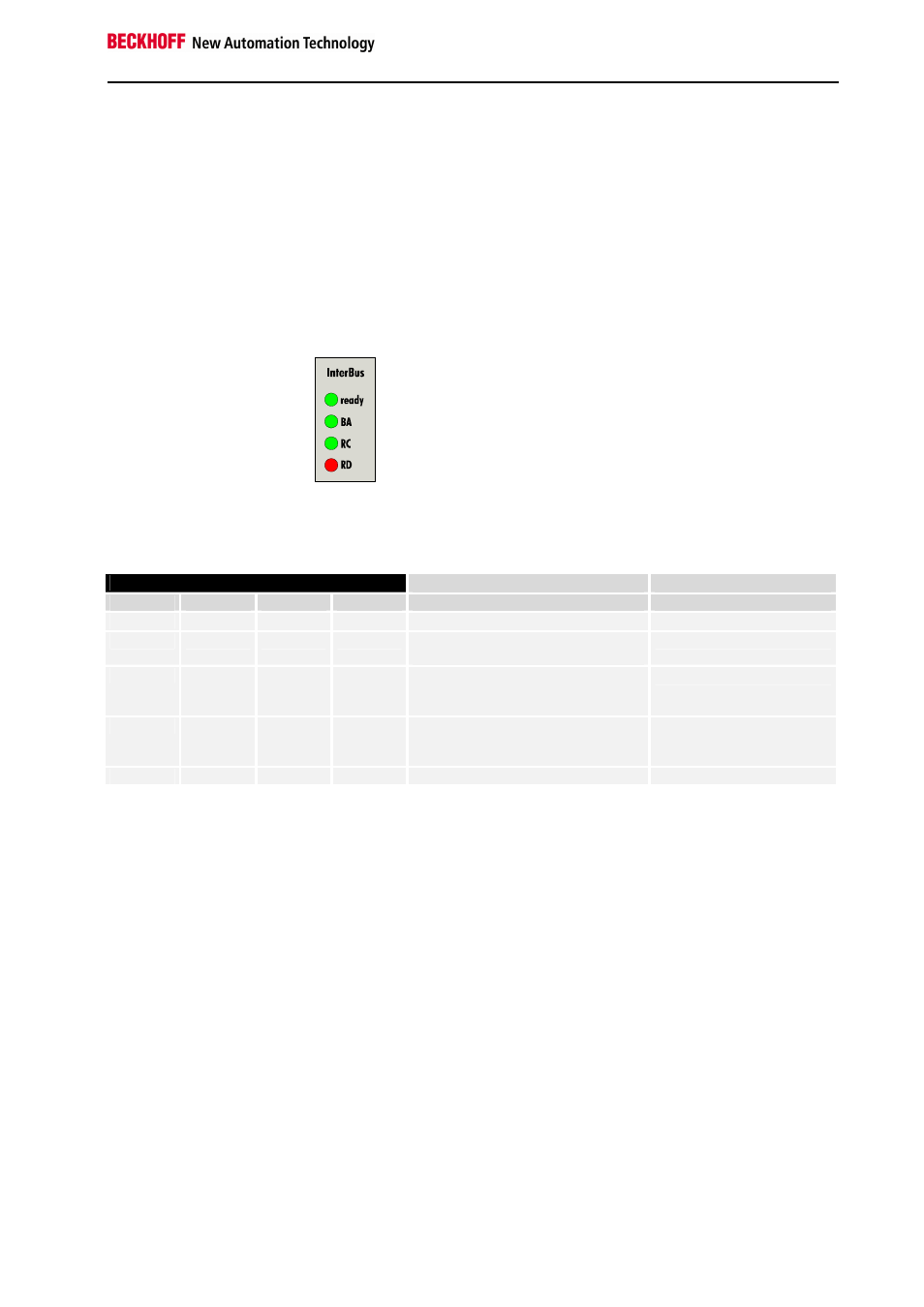
The top four LEDs indicate the operating states of InterBus communication.
The bottom two LEDs indicate local communication between the bus cou-
pler and bus terminals (as explained above).
However, there is a relationship between the bottom green I/O RUN-LED
and the field bus when the bus coupler is switched to the „SYNCHRO-
NOUS“ mode. Then the I/O RUN-LED only lights up in connection with
access on the internal K-Bus. That is to say, the green I/O RUN-LED does
not light up until data exchange via the field bus is commenced. This me-
ans that the field bus must access the bus coupler. This relationship does
not apply in the bus coupler’s default setting (FREERUN). In this state, the
I/O RUN - LED is independent of the InterBus status.
The fieldbus status LEDs indicate the operating states of the field bus. The
functions of the InterBus system are indicated by the „ready“, „BA“, „RC“
and „RD“ LEDs.
The meanings of the LEDs on the BK4000
ready
BA
RC
RD
Meaning
Remedy
lit
off
off
off
The bus coupler is ready
lit
lit
lit
off
Remote bus active
Data transfer with Master running
lit
off
lit
off
Incoming field bus connection has
been established,
no connection
lit
lit
off
lit
Continuing remote bus is off, owing
to a cable fault or deactivated by the
Master
Search for a cable disconti-
nuity or a short-circuit of the
master.
off
off
off
off
No function, power failure
The green I/O LED lights up in connection with access to the internal K-
Bus. However, the bus coupler interrogates the configuration of the bus
terminals after power on and does not perform a data exchange with the
terminals. That is to say, the red I/O LED goes off after an error-free start
up without the green I/O LED having to light up. The green I/O LED does
not light up until data exchange is begun (see above).
ID code and ID length
ID code and ID length
Structure of the InterBus ID
code
In the ID cycle, which is run through to initialise the InterBus system, the
connected stations inform each other of their functions and their byte
lengths. After switching on, the InterBus coupler determines its length in
the InterBus during the initialisation phases of the bus terminals and gene-
rates a corresponding ID code. The InterBus coupler reports as a digital or
analog „external coupler“ of variable length. The length results from the
nature and number of fitted bus terminals.
The InterBus ID code consists of 2 bytes. The MSB describes the length of
the data words that are transferred. Bits 13, 14 and 15 can transfer messa-
ges. The LSB describes the type of the bus station in relation to the signal
type and other features such as remote bus / peripheral bus station, PPC,
ENCOM or DRIVECOM. The InterBus coupler BK4000 uses six IDs for
inputs / outputs, inputs and outputs (x1hex, x2hex, x3hex). The IDs are