BECKHOFF BK4000 User Manual
Page 26
Annex
26
BK4000
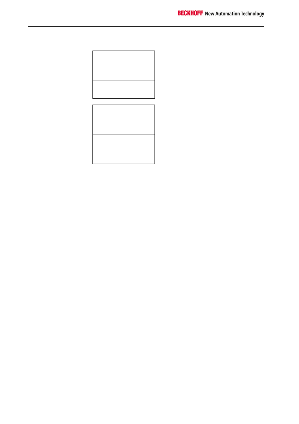
Overview of the process image breakdown in the bus coupler:
Output data in the
bus coupler
A0
...
byte oriented data
...
A11
A12
bit oriented data
A13
Input data in the
bus coupler
E0
...
byte oriented data
...
E7
E8
...
bit oriented data
...
E10
The base addresses E0 and A0 listed here apply as relative addresses or
addresses in the bus coupler. In the bus master software, a base periphe-
ral address may be assigned to the base address of the bus coupler. All
following addresses are automatically assigned the successive addresses
depending on the length of the actual data words.
Firmware version 4.0 and higher of the InterBus interfaces:
The bus master may place the addresses in a freely chosen location in the
controller’s process image. The masters’s configuration software enables
any chosen assignment of the bytes to the addresses of the process image
in the controller.
Representation of analog signals in the
process image
Each analog channel consists of three input bytes and three output bytes.
In the standard case, however, an analog channel only requires one data
word in the process image. These two bytes represent the value as a
signed integer, i.e. 15 bits with sign. The data format is used regardless of
the actual resolution. For example: in the case of a resolution of 12 bits, the
four least significant bits are of no relevance. By means of the KS2000
configuration software, the third byte can be inserted in the process image
for any channels. The least significant byte has control and status functons.
Various operating modes can be set with the control byte. The six least
significant bits can be used as addressing bits. Addressing serves to read
and write a register set. The register set has 64 registers and allows setting
of different operating parameters, for example selection of a thermocouple
type or representation of a value in a different numerica format.