Setting the transmission rate, Setting the cable length – BECKHOFF BK7500 User Manual
Page 19
Basic information
BK7500
19
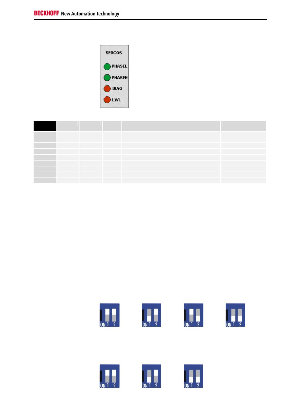
Diagnostic - LEDs of the
BK7500
I / O RUN
PHASEL
PHAESH
Optical
fibres
Meaning
Remedy
lit
lit
lit
off
Telegrams are passing cyclically along the ring
Inputs are read and outputs are set.
lit
off
lit
off
The SERCOS ring is in phase 3
lit
lit
off
off
The SERCOS ring is in phase 2
off
lit
off
off
The SERCOS ring is in phase 1
off
off
off
off
The SERCOS ring is in phase 0
Attention must be paid to the fact that there is a connection between the
green I/O LED and the field bus. The I/O LED lights up in connection with
access to the internal K-bus. The green I/O LED does not light up until a
trigger begins via the field bus. This means that the field bus must access
the bus coupler and the controller software must clear a cyclical trigger.
The green I/O LED indicates access to the internal K-bus and is reset after
100 ms.
The bus coupler queries the configuration of the bus terminals after
switching on and does not exchange data with the terminals. That is to say,
the red I/O LED goes off after an error-free startup without the green I/O
LED having to light up. The green I/O LED does not light up until data
exchange is begun via the Beckhoff-Lightbus.
Setting the Transmission Rate
Setting the transmission
rate in the BK7500
2 Mbd
4 Mbd
8 Mbd
16 Mbd
Setting the Cable Length
The cable length is set at the coupler in the following stages: 0...15, 15...30
and 30...45 m. This is necessary in order to adapt the transmission power
to the cable attenuation.
Setting the cable length to
the next device
0 .. 15 m
15 .. 30 m
30 ..45 m