Periphery level, Bus terminals bus coupler field bus 24 v dc – BECKHOFF BK7500 User Manual
Page 8
Basic information
8
BK7500
Fieldbus connection
SERCOS Fibre optic
Plug SERCOS Z1003
There is a recessed front face on the left hand side. The typical SERCOS
connecting plugs can be inserted here. SERCOS consists of a fiber-optic
conductor ring into which the bus coupler is inserted. You need a fiber-
optic conductor connector type SERCOS Z1003 for connection.
Configuration interface
Serial interface under the
front flap
On the lower part of the front face you will find the standard bus couplers
which are fitted with an RS232 interface. The miniature plug can be
attached to a PC by means of a connection cable and the configuration
software KS2000. This interface enables you to configure the bus terminals
, e.g. setting the amplification factor of the analog channels. The mapping
of the bus terminal data to the process view in the bus coupler can be
changed via the interface. You can also access the functionality of the
configuration interface via the fieldbus by means of the ADS
communications.
K-bus contacts
6 contacts at the side
The connections between the bus coupler and the bus terminals are
effected by gold contacts at the right-hand side of the bus coupler. When
the bus terminals are plugged together, these gold contacts automatically
complete the connection to the bus terminals. The K bus is responsible for
the power supply to the electronic components of the K bus in the bus
terminals, and for the exchange of data between the bus coupler and the
bus terminals. Part of the data exchange takes place via a ring structure
within the K bus. Disengaging the K bus, for example by pulling on one the
bus terminals, will break this circuit so that data can no longer be
exchanged. However, there are mechanisms in place which enable the bus
coupler to locate the interruption and report it.
Supply isolation
3 supply groups:
fieldbus
K-bus
peripheral level
The bus couplers operate with three independent supplies. The input
power supplies the electrically isolated K-bus circuitry in the bus coupler
and the K-bus itself. The power supply is also used to generate the
operating power for the fieldbus.
Note: All the bus terminals are electrically isolated from the K bus, so that
the K-bus is completely electrically isolated.
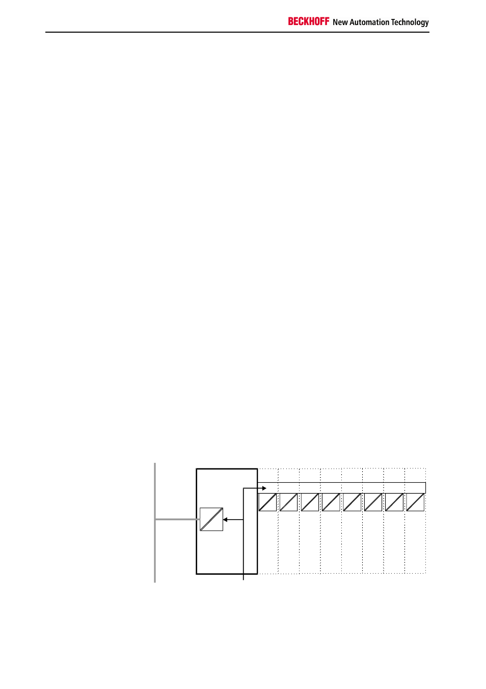
Setting up the power levels
in the bus terminal system
Periphery level
Bus terminals
Bus coupler
Field bus
24 V DC
Terminal bus