Electrical data – BECKHOFF BK8000 User Manual
Page 11
Basic information
BK8000
11
Insulation test
PE power contacts
The connection between bus couplers and bus terminals is automatically
effected by latching the components together. The K bus is responsible for
passing data and power to the electronic components of the bus terminals.
In the case of digital bus terminals, the field logic receives power via the
power contacts. Latching the components together has the effect that the
series of power contacts constitutes a continuous power track. Please refer
to the circuit diagrams of the bus terminals: some bus terminals do not loop
these power contacts through, or not completely (e.g. analog bus terminals
or 4-channel digital bus terminals). Each power input terminal interrupts the
series of power contacts and constitutes the beginning of a new track. The
bus coupler can also be used to supply power to the power contacts.
The power contact labeled "PE” can be used as protective earth or ground.
This contact stands proud for safety reasons and can carry short-circuit
currents of up to 125 A. Note that in the interests of electromagnetic
compatibility the PE contacts are capacitively connected to the supporting
track. This may lead to spurious results and even damage to the terminal
when you test the insulation (e.g. insulation test for breakdown using a
230 V mains supply to the PE line). You should therefore disconnect the
PE line on the bus coupler while you carry out insulation tests. You can
disconnect other power supply points for the duration of the test by drawing
the power supply terminals out from the remaining row of terminals by at
least 10mm. If you do this, there will be no need to disconnect the PE
connections.
The protective earth power contact ("PE”) may not be used for any other
connections.
Electrical data
The electrical data of the RS 485 bus coupler is listed in this chapter. The
bus coupler is set to a baud rate of 38400 baud. Addresses from 0 to 99
can be set by means of two address selectors on the coupler. The
following table provides an overview of all data.
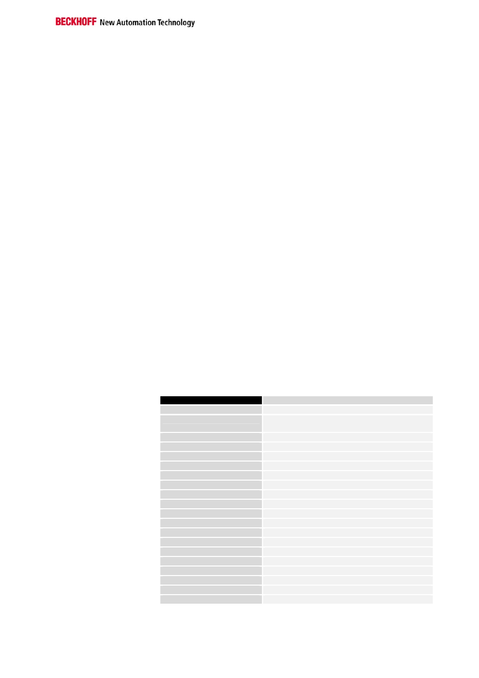
Technical data
BK8000
Voltage supply
24 V DC (20 ...29 V DC)
Input current
70 mA + (total K-Bus current)/4
500 mA max.
Output current K-Bus
1750 mA max.
Number of bus terminals
64
Digital peripheral signals
256 inputs/outputs
Analog peripheral signals
128 Ein-/ Ausgänge
Maximum number of bytes
512 Byte I and 512 Byte O
Station adress
selectable up to 99 via DIP switches
Baud rate
38400 Baud
Power contact voltage
24 V DC / AC
Power contact current load
10 A
Dielectric strength
500 Veff (Power contact / supply voltage)
Weight approx.
170g
Operating temperature
0°C ... +55°C
Storage temperature
-20°C ... +85°C
Relative humidity
95%, no condensation
Vibrations/shock resistance conforms to IEC 68-2-6 / IEC 68-2-27
EMC resistance burst / ESD conforms to EN 50082 (ESD, Burst) / EN 50081
Installation position
any
Type of protection
IP20
Current consumption on the
K-Bus
For operation of the K-bus electronics, the bus terminals require energy
from the K-bus that is supplied by the bus coupler. Refer to the catalog or
the corresponding data sheets of the bus terminals for details of the K-bus