System presentation – BECKHOFF BK8000 User Manual
Page 16
RS 485 Coupler BK8000
16
BK8000
RS 485 Coupler BK8000
System presentation
General
Beckhoff KS8000:
BKcom-OCX
The BK8000 bus coupler enables the establishment of a simple data bus
working on a RS 485 transfer basis. By using repeater, up to 99 bus
coupler can be connected to a bus. The RS 485 coupler is usually
connected to the PC via the serial interface. For the case that the PC does
not have a RS 485 interface the use of a interface converter RS232/RS485
is possible.
Communication with the bus coupler is based on the master/slave
principle, i.e. there is only one central station (the master), which controls
access. The slaves are only permitted to send at the master's request. The
master must request (poll) the data of the slaves (bus couplers) cyclically.
At the same time, the station is assigned a station address (adjustable by
rotary switch on the bus coupler) by way of which the master is able to
address the respective station. Here, the master is always assigned the
address 0, and the address 1-99 can be used by the slaves.
During the exchange of data with the bus couplers, complete process
images are always exchanged, i.e. the master sends the complete output
data to the bus couplers and receives the input data of the bus terminals
back from the couplers.
A software driver for Windows95/NT is available for communication with
the bus coupler. This „Beckhoff KS8000: Bkcom-OCX“ provides
functionality with which a simple connection can be established from the
PC's serial interface to the bus coupler. This OCX can be used by all
programming languages that operate on the basis of the Microsoft
Component Object Model (COM) specifications. You will find further
explanations in the manual on the „KS8000: BKcom-OCX“.
Master/Slave
Communication between
two bus couplers
It is possible to establish autonomous master/slave communication
between two bus couplers. To do this, the master bus coupler must be set
with the station address 0 and the slave bus coupler must be assigned the
address 1. This enables a simple "complementary" exchange of data
between two couplers. During such a data transfer, the master transfers its
input data to the output terminals of the slave and outputs the slave's input
data to its own output terminals. In this case, attention must be paid to
ensuring that all data is complementary, i.e. the master must transfer the
number of output data words to the slave that the slave possesses as input
data words. The master must receive the same number of input data words
as the number that it is capable of forwarding to the terminals as data
output words.
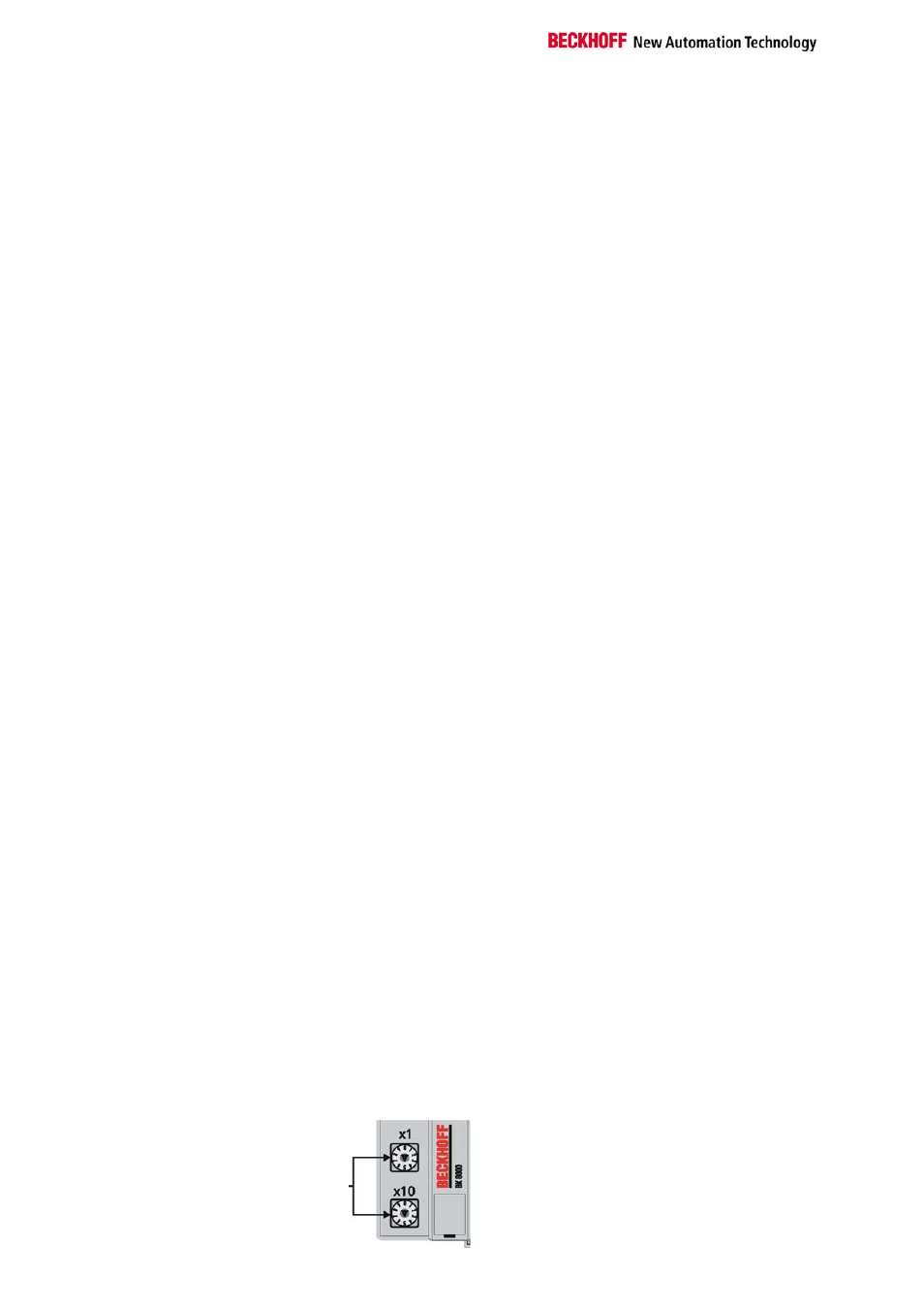
Setting the station
addresses
The station address is set by means of the rotary switches on the left side
of the bus couplers. The address is set as a decimal number. The top
rotary switch is the units power and the bottom one is the tens power of the
address (example: station address 18: bottom rotary switch =1, top rotary
switch = 8). The bus coupler must be reset (by brief interruption of the
power supply or by software reset) to ensure that the rotary switch settings
are stored by the bus coupler.
Address selector
Address-
selector