BECKHOFF BK8000 User Manual
Page 19
RS 485 Coupler BK8000
BK8000
19
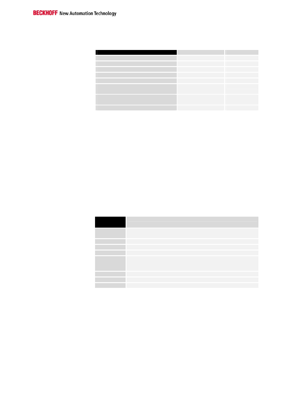
Response
In its response, the bus coupler answers the request by the master.
Description of the response
Byte
Value range
Start identifier
0
’p‘ (0x70)
Number of process data input words
1
0 – 255
Message ident
2
0 –255
Multipoint Addresse
3
0 – 99
Status
4
0 – 255
Process data input LOW Byte
( optional )
5 + 2 x n
(n = 0,1,2,..., 125)
0 – 255
Process data output HIGH Byte
( optional )
6 + 2 x n
0 – 255
Checksum
6 + 2 x n + 1
0 – 255
The "start identifier" consists of one byte and identifies the start of a data
packet. The "number of process data input words" specifies the size of the
input process image in the bus coupler in words. If the number of bytes of
the process image is odd, the bus coupler enters a dummy byte before the
checksum.
The corresponding value of the request string is entered as the "message
ident".
The "multipoint address" corresponds to the master address 0. The status
byte contains information about the status of the bus coupler (see table).
If available, the "process data inputs" are entered as data words in INTEL
format.
The "checksum" is generated by adding up the contents of the individual
bytes (complete response string without checksum byte). Any occurring
overflow is ignored.
Status byte of the bus
coupler
Bus coupler
status byte
Error (Bit = 1)
Status.0
Terminal bus error: an error has occurred in data communication
with the terminals
Status.1
Configuration error: see occur codes 1 and 2 (page 13)
Status.2
--
Status.3
--
Status.4
Invalid process data output length: the received number of process
output words is unequal to the physically existing data length on the
K bus.
Status.5
--
Status.6
--
Status.7
--
Example
The BK8000 is connected to a PC via the RS 485 interface. The address 5
has been set on the coupler.The coupler has been expanded with the
following terminals (the mapped bits in the process image of the bus
coupler are given in brackets):
3 x KL1002 (digital input terminal 3 x 2 input bits = 6 bits I)
2 x KL1114 (digital input terminal 2 x 4 input bits = 8 bits I)
1 x KL3002 (analog input terminal 2 x 16 bits I)
1 x KL9200 (potential infeed terminal 24 V DC, no I/O bits in the PI)
4 x KL2012 (digital output terminal 4 x 2 output bits = 8 bits O)
1 x KL4002 (analog output terminal 2 x 16 bits O A)
1 x KL9010 (end terminal, no I/O bits in PI)