BECKHOFF BK8000 User Manual
Page 15
Basic information
BK8000
15
Communication errors
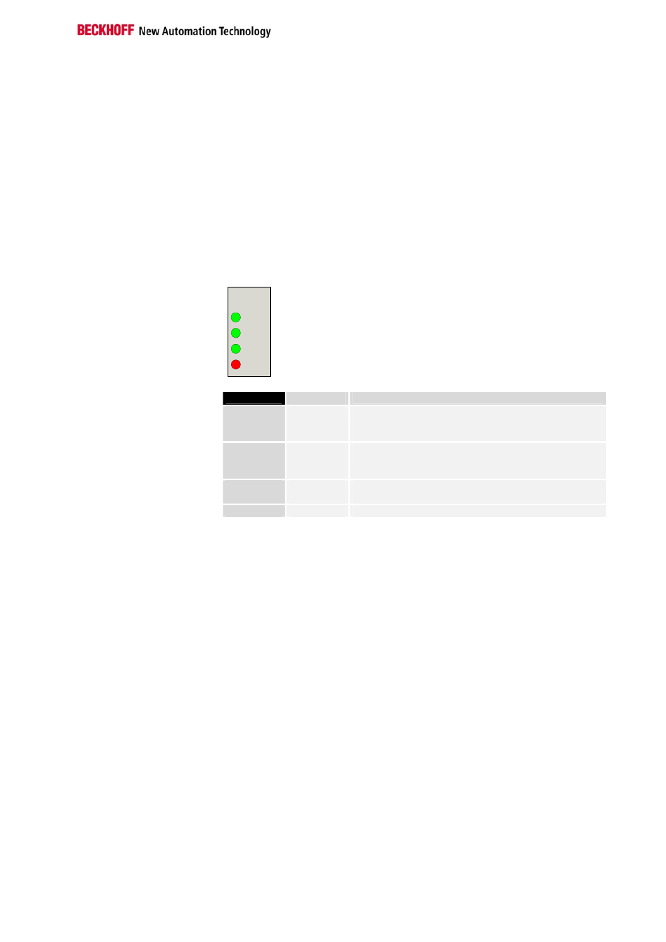
The top four LEDs show the operating states of RS485 communication.
The two bottom LEDs indicate local communication between the bus
coupler and bus terminals (as explained above).
There is nevertheless a relationship between the bottom green I/O RUN
LED and RS485 communication when the bus coupler is switched to the
'Synchronous mode'. Then, the I/O RUN LED only lights up in connection
with access to the internal K bus, i.e. the green I/O RUN LED does not light
up until data transfer is commenced via the RS 485 connection. This
means that the bus coupler must be accessed. This relationship does not
apply in the bus coupler's default setting (Freerun). In this status, the I/O
RUN LED is independent of the communication status of the serial
communication link. The 4 communication LEDs indicate the status of RS
485 transfer. The operating states are indicated by the „WD“, „RX“, „TX“
and „ERROR“ LEDs.
WD
RX
TX
ERROR
RS 485
LED
Operating state
WD
Off
A watchdog timer overflow has occurred. No data is
exchanged with the coupler during the set watchdog
time.
RX
Flashing,
flickering
Data is being received from the bus coupler via the
interface.
TX
Flashing,
flickering
Data is being transceived from the bus coupler via the
serial interface.
ERROR
Lit
A data transfer error has occurred (e.g. parity error).
The green I/O LED lights up in connection with access to the internal K
bus. However, the bus coupler queries the configuration of the bus
terminals after switching on and does not exchange any data with the
terminals. That is to say, the red I/O LED goes off after an error-free
startup without the green I/O LED having to light up. Then, the green I/O
LED does not light up until data transfer is commenced (see above).