4 control and status byte – BECKHOFF KL5111-0000 User Manual
Page 15
Register description
KL5111-0000
13
3.4 Control and Status Byte
3.4.1 Process data exchange
3.4.1.1
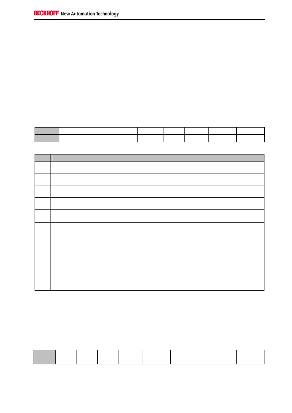
Control-Byte during process data exchange
The control byte is transferred from the controller to the terminal. It can be used in the register mode
(RegAcc = 1) or during process data exchange (RegAcc=0). Various actions are triggered in the KL5111
with the control byte:
Bit
CB.7 CB.6 CB.5 CB.4 CB.3
CB.2 CB.1 CB.0
Name
RegAcc
- - - -
Cnt_Set
RD-Period
En_Latch
Bit
Name
Function
CB.7 RegAcc=0 Process
data
exchange
CB.6 -
reserved
... ...
...
CB.3 -
reserved
CB.2 Cnt_Set
The counter is set with a rising edge of Cnt_Set to the value that is specified via the
process data.
CB.1 RD-Period
If CB.1 is set and Bit R32.8 of Feature Register is not set:
The periods between two positive edges of the input A are measured with a
resolution of 200 ns and displayed at data bytes DataIN2, DataIN3 and DataIN4.
If CB.1 and Bit R32.8 of Feature Register is set:
The pulses within a time window defined by R33 are counted and displayed at data
bytes DataIN3 and DataIN4.
CB.0 En_Latch
The zero point latch (C input) is activated. With the first external latch pulse after
the validity of the En_Latch bit, the counter value is stored in the latch register (this
has priority over En_LatchX). The following pulses have no influence on the latch
register when the bit is set (not used if the V/R mode is active, i.e. bit 15 is set in
the feature register).
3.4.1.2
Status-Byte during process data exchange
The status byte is transferred from the terminal to the controller. The status byte contains various status
bits of the KL5101.
Remark: the signal bits A, B, C are output in the data byte D2 (bits 3, 4, 5)
Bit
CB.7 CB.6 CB.5 CB.4 CB.3
CB.2
CB.1
CB.0
Name
RegAcc -
-
Overflow Underflow CntSet_Acc RD_Period_Q Latch_Val