3 terminal configuration – BECKHOFF KL5111-0000 User Manual
Page 8
Product Overview
6
KL5111-0000
2.3 Terminal configuration
The terminal can be configured and parameterized via the internal register structure.
Each terminal channel is mapped in the bus coupler. The data of the terminal is mapped differently in the
memory of the bus coupler depending on the type of the bus coupler and on the set mapping
configuration (e.g. Motorola/ Intel format, word alignment,...).
Contrary to the analog input and output terminals, in the case of the KL5111 the control and status byte is
always mapped regardless of the higher-level field bus system.
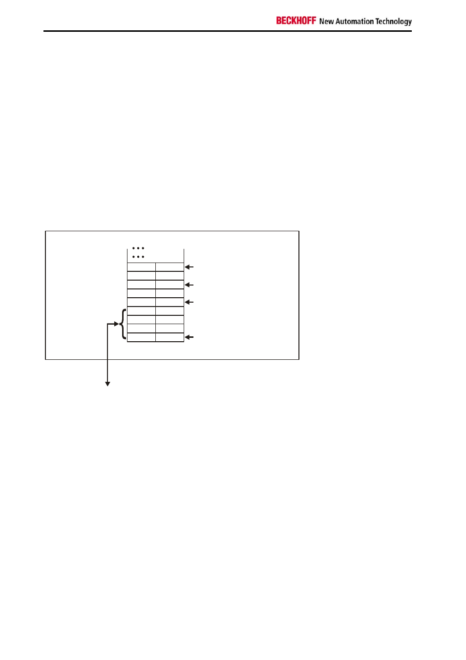
Lightbus Coupler BK2000
In the case of the Lightbus coupler BK2000, the control /status byte is also always (ie. in the case of all
analog terminals) mapped in addition to the data bytes. It is always in the low byte at the offset address of
the terminal channel.
0
Offset Terminal 1= 0
KL5111
Offset Terminal2 Channel1= 4
Offset Terminal2 Channel2= 6
Offset Terminal3 Channel1 = 8
User data allocation depending
on mapping.
K-Bus
Beckhoff-Lightbus
bus coupler
BK2000
To the bus terminal
L
H
C/S
D1
-
-
Data L
Data L
D3
D0
D2
Data H
Dat H
D4
C/S
C/S
C/S
The terminal is
mapped in the
bus coupler.