BECKHOFF KL5111-0000 User Manual
Page 17
Register description
KL5111-0000
15
3.4.2 Register
Communication
When bit 7 of the control byte is set, the first two bytes of the user data are not used for process data
transfer, but are written into or read out of the terminal’s register.
In bit 6 of the control byte, you define whether a register is to be read or written. When bit 6 is not set, a
register is read without modification. The value can be taken from the input process image.
When bit 6 is set, the user data is written into a register. The operation is concluded as soon as the status
byte in the input process image has supplied an acknowledgement (see examples).
The address of the register to be addressed is entered in bits 0 to 5 of the control byte.
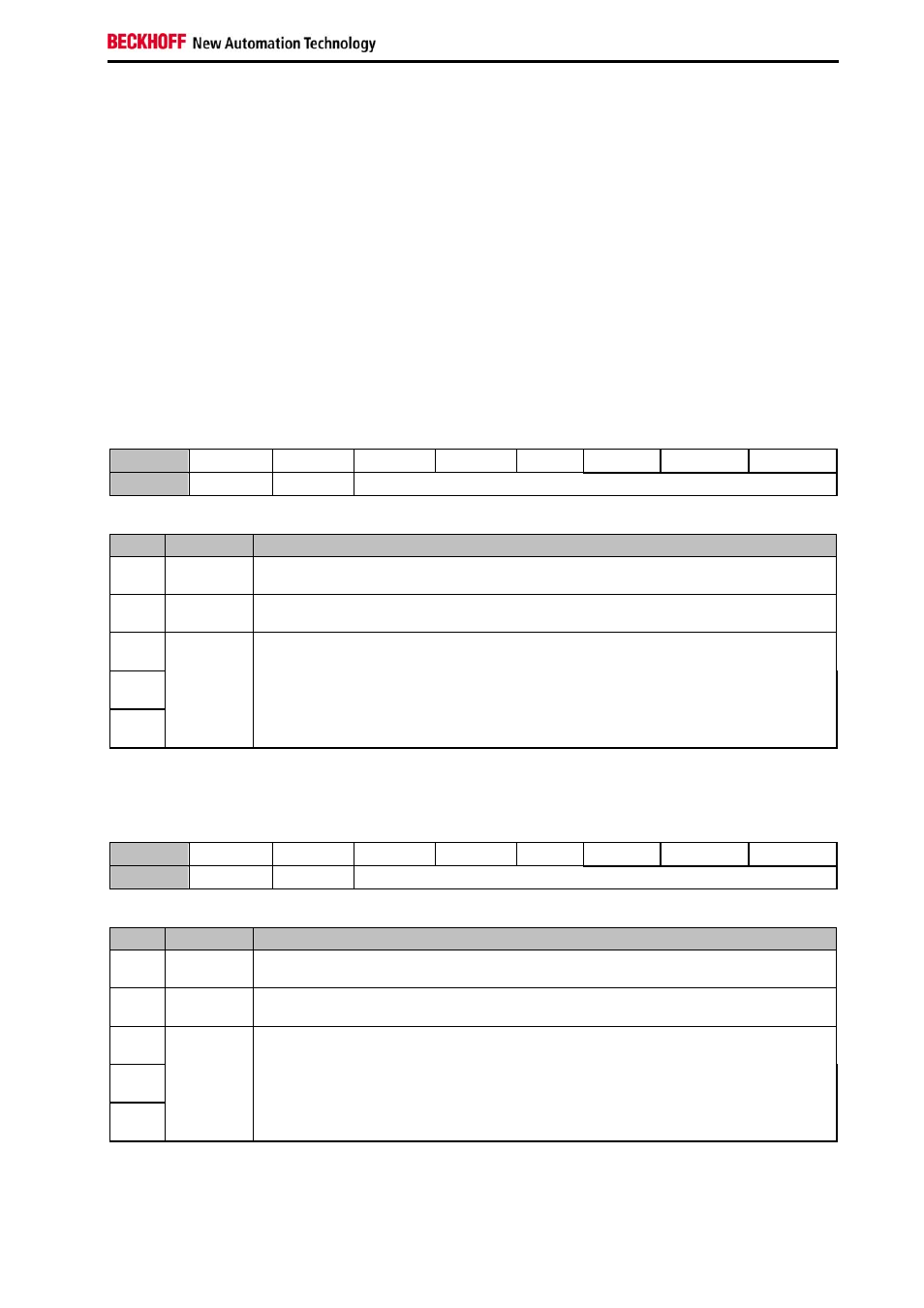
3.4.2.1
Control byte during Register Communication
Bit
CB.7 CB.6 CB.5 CB.4 CB.3
CB.2 CB.1 CB.0
Name
RegAcc R/W
Reg-No.
Bit
Name
Function
CB.7 RegAcc=1 Register
Communication
CB.6
R/W
Bit 6=0: read, Bit 6=1: write
CB.5
...
CB.0
Reg-No.
Register number of the register that is to be read or written
3.4.2.2
Status byte during Register Communication
Bit
SB.7 SB.6 SB.5 SB.4 SB.3
SB.2 SB.1 SB.0
Name
RegAcc R/W
Reg-No.
Bit
Name
Function
CB.7
RegAcc=1 acknowledge for Register Communication
CB.6
R/W
Bit 6=0: read
CB.5
...
CB.0
Reg-No.
Register number of the register that has been read or written