Start-up procedure and diagnostics – BECKHOFF FM33xx User Manual
Page 18
Functional description
FM33xx
13
Start-up procedure and diagnostics
Installation guidelines
The PROFIBUS Nutzerorganisation e.V. technical guidelines must be
followed when installing and laying the PROFIBUS lead.
PROFIBUS-DP/FMS assembly guidelines
www.profibus.com
Operating modes
After being switched on, the TC-Plug carries out a self-test, and checks all
the functions of its components. If there is a fault, the TC-Plug enters the
"STOP" mode, but otherwise goes into the "fieldbus start" state.
Status display LEDs
The module has two groups of LEDs for the display of status. The upper
group contains three LEDs and indicates the state of the PROFIBUS, while
the lower group indicates the states of the thermocouple inputs.
RUN LED
The “RUN” LED is illuminated cyclically by process data exchange over the
fieldbus.
BF LED
The “BF" LED indicates any fieldbus errors.
ERR LED
The “ERR" LED indicates the error code of any fieldbus error.
TC RUN
The “TC RUN” LED is illuminated cyclically by process data exchange.
TC ERR
The “TC ERR” LED indicates the error code for the thermocouple inputs.
Local errors
The bottom two LEDs are used to indicate the operating status of the
thermocouple inputs. The green LED lights up in order to indicate fault-free
operation. The red LED blinks with two different frequencies in order to
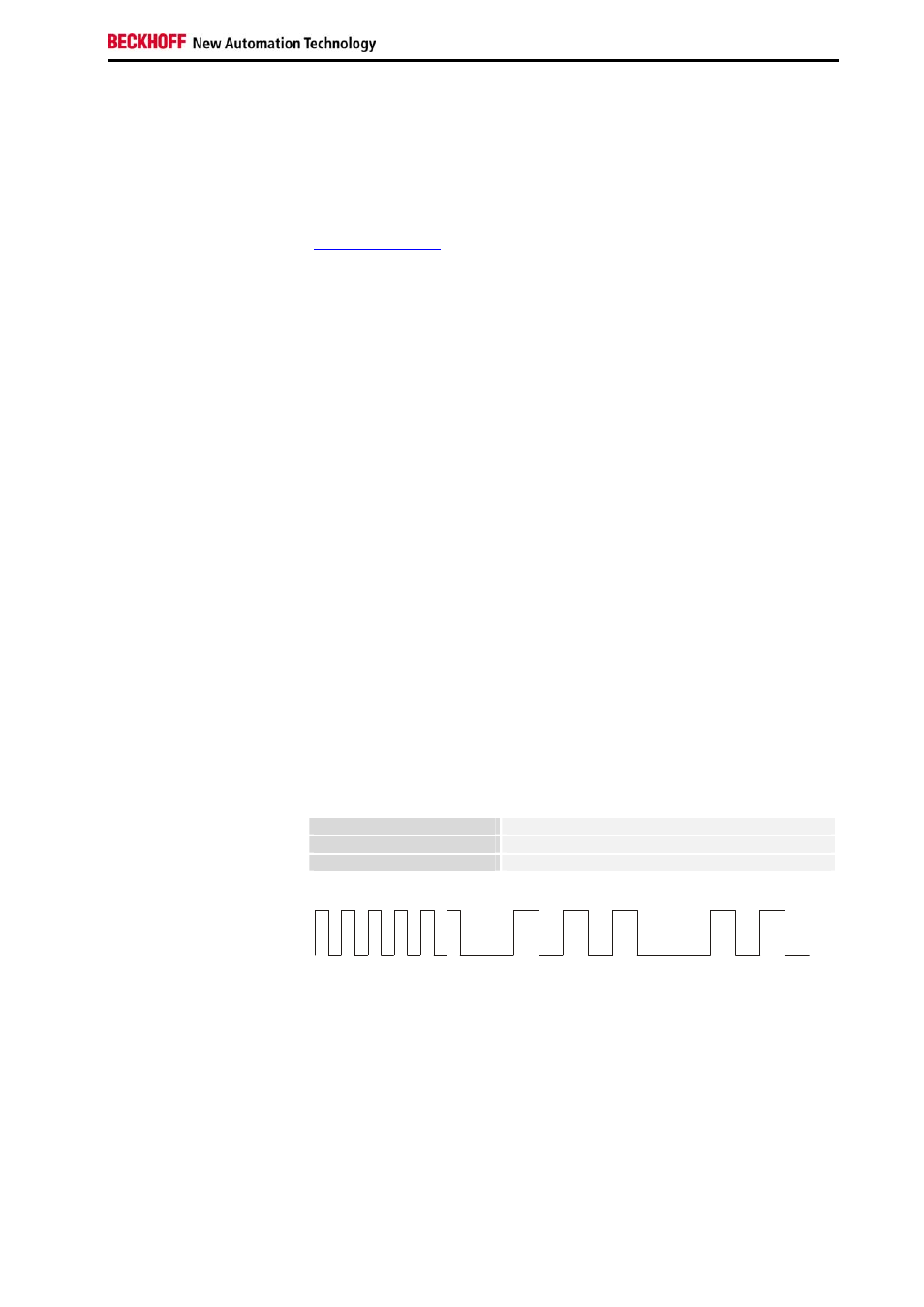
indicate an error. The error is encoded in the blinks as follows:
Fast blinking
Start of the error code
First slow sequence
Error code
Blink code
Second slow sequence
Error code argument
Start of the error code
Error type
Error location