1 installation, Wall mount – Belshaw Adamatic Type B Donut Cutter User Manual
Page 17
Belshaw Bros., Inc.
• www.belshaw.com • Phone 206-322-5474 • Fax 206-322-5425
Type B Donut Cutter TS
MN-1528EN
1
1 Installation
Wall Mount
When the donut cutter is to be mounted on a wall
bracket, it is mandatory to provide a good, solid
support on the wall. For this purpose, we
suggest using a 2” x 4” or 2” x 6” timber of good
quality. The timber should extend from the
ceiling to the floor. The timber must be secured
with #4 wood screws, 4” long mini8mum,
screwed directly into a wall stud. The screws
should be located approximately every 12” over
the entire length of the timber.
After attaching the 2” x 4” or 2” x 6” timber as
described above, do the following:
1. Position the fryer 6” to 8” from the wall
and slightly to the right or left of the
timber support. Level the fryer.
2. Lay a straight edge (a board will do)
across the kettle top to the wall support
and mark the height of the kettle top on
the wall support.
3. Find the point in the center of the wall
support and 15” above the kettle height.
Drill a ¼” diameter hole at this point and
attach the wall plate to the wall support
with a 5/16” x 1 ½” lag screw through the
top hole in the wall plate.
4. Check to see that the wall plate is vertical
(use a level if available). Then, secure
the wall plate with the five remaining lag
screws.
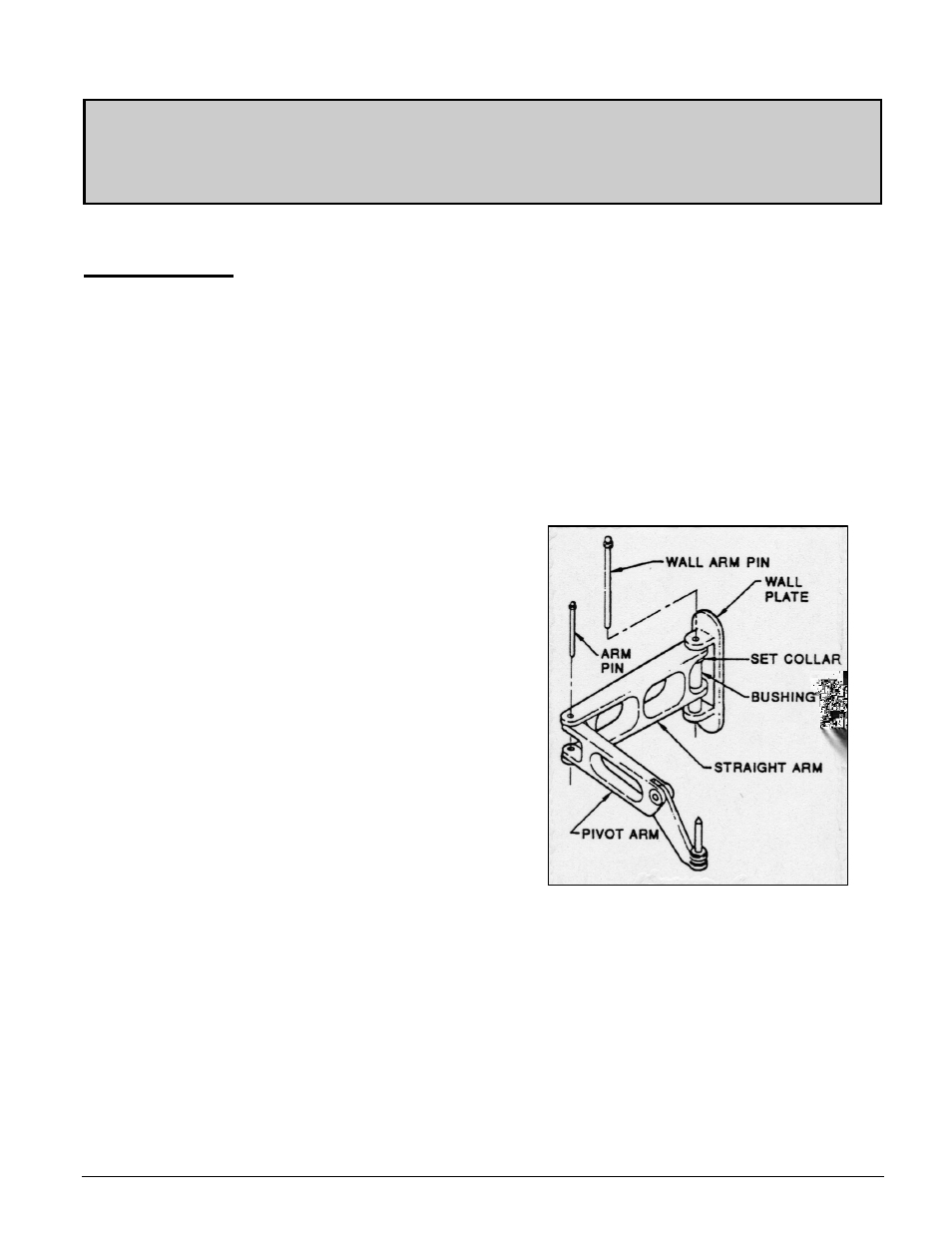
5. To connect the straight arm section to the
wall plate: First slide the bushing
through one leg of the straight arm, slide
set collar onto the bushing (pin side
down); then slide the bushing through the
hole in the other leg of the straight arm.
Position the bushing between the hinge
brackets on the wall plate and pass the
wall pin through hinge brackets and
bushing (See Figure 1).
6. The pivot arm is connected to the straight
arm by passing the arm pin through both
arm sections, with the legs of the pivot
arm between the legs of the straight arm
(See Figure 1).
7. The cutter frame can now be mounted on
the pin at the end of the pivot arm.
Figure 1