4 flow-bus installation and addressing, 1 installation, 2 automatic installation to flow-bus – Bronkhorst FLOW-BUS interface User Manual
Page 19: Flow‐bus installation and addressing, Nstallation, Automatic installation to flow‐bus, 4 flow‐bus installation and addressing
BRONKHORST
®
4 FLOW‐BUS INSTALLATION AND ADDRESSING
4.1 I
NSTALLATION
All modules in a FLOW‐BUS system must have their own address. FLOW‐BUS systems will not function properly when
there are more modules on the same address. To avoid this, modules will do a check before getting operational on
their bus‐address and give a message when this address is occupied. If you receive a complete FLOW‐BUS system from
Bronkhorst all modules have been installed to the bus already (in one system). Each time you power‐up your system
afterwards, the modules will start‐up on the same address on the bus, because these settings are stored in their non‐
volatile memory. So if you receive a new system, normally you only have to connect the cables and switch on the
power.
Page 19
FLOW‐BUS interface
9.17.024
See document 9.17.023 for a more information.
This document can be found at:
If a new module has to be connected to a bus system, it needs a free address. Normally this will be the first free
address counted from address 3. Address 0 is reserved for the start‐up procedure. Address 1 is reserved for an
interface module to (personal) computers and address 2 has been reserved for operation modules like E‐7000. There
are four ways to add a new module to your bus system:
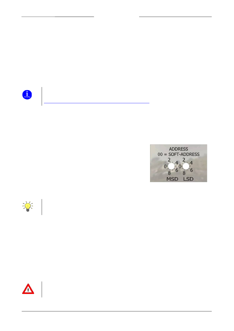
4.1.1 Install to bus via rotary switches on the side of the instrument (if present).
On the side of the instrument are rotary switches placed and a label with the
explanation of the switches. Make sure to use a screwdriver which is suited
for the switches.
The switches have the following function:
NODE ADDRESS (00 – 99)
With the NODE ADDRESS switch, the instruments address can be set. The MSD is the high part of the decimal number
and the LSD the low part. For instance address 25 means MSD on 2 and LSD on 5.
The default switch position is 00. In this position the address is software programmable.
The default software programmable address is 3.
During instrument initialisation, the node address switches are read. If the switches specify a valid FLOW‐BUS address,
i.e. a value from 3 to 99, this value is used.
If the specified address differs from the value stored in the instrument, the new address is saved in memory.
If the switches specify an invalid FLOW‐BUS address, i.e. a value of 1 or 2, the value stored in the instrument’s memory
will be used as the address.
4.1.2 Automatic installation to FLOW‐BUS
Most FLOW‐BUS modules have the facility to install themselves automatically on the bus. This means that they are
able to find the first free node‐address counted from 3 and connect themselves to the bus. This action can be started
by means of a manual interface on the module. Directly afterwards the new module will be part of the FLOW‐BUS
system.
Make sure to install only one new module at the same time.