Main outputs, Connectivity, Auxiliary/moh output – Cloud Electronics CX261 User Manual
Page 11: Source selection
CX261 User Manual v1.3
11
11
Main Outputs
The main LEFT and RIGHT outputs on the CX261 are
electronically balanced and can operate into loads down to
1.2 kΩ. The nominal output level is 0 dBu (775 mV
rms
) but
the mixer can drive a maximum output level of +20 dBu
(7.75 V
rms
).
Connectivity
The outputs are on rear panel 3-pin 3.5 mm-pitch
screw terminal connectors (
11
on fig. 3). For balanced
connections, 2-core screened cable should be used. Connect
as shown below.
1 2 3
fig.8: Balanced output wiring
CX261 balanced output:
pin 1 ground
pin 2 cold
pin 3 hot
+
+
-
-
Balanced input (e.g. XLR):
pin 1 ground
pin 2 hot
pin 3 cold
1
2
3
Unbalanced connection may be used if necessary, but its use
is recommended only between pieces of equipment in the
same rack. Unbalanced signals should not be run over long
distances. An unbalanced output connection should be wired
as shown below:
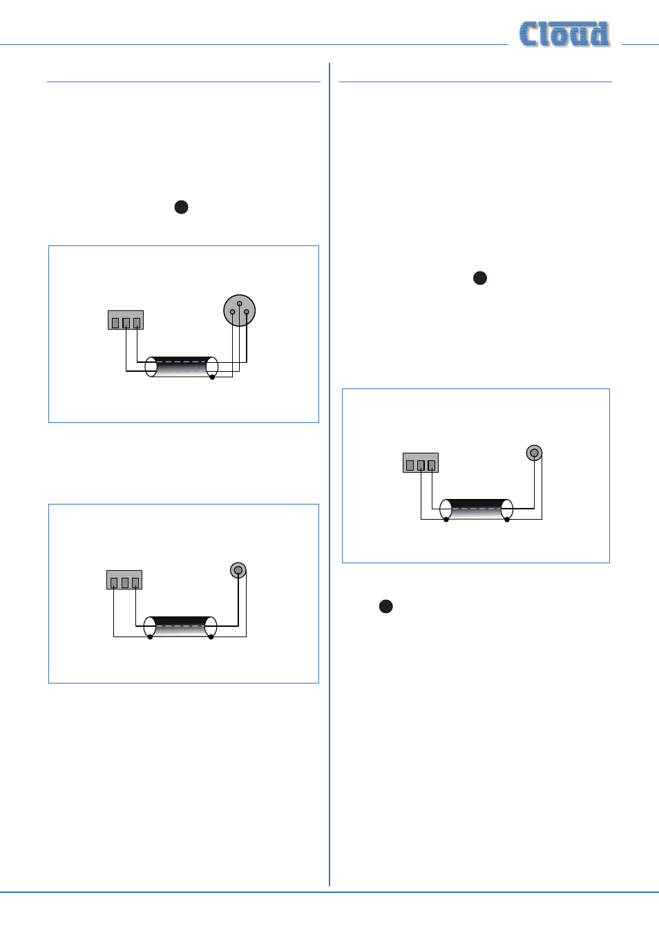
1 2 3
fig.9: Unbalanced output wiring
CX261 balanced output:
pin 1 ground
pin 2 cold
pin 3 hot
+
+
SCN
SCN
Unbalanced input (e.g. phono)
Note that pin 2 of the output connector is not used.
Auxiliary/MOH Output
The MOH (Music On Hold), or auxiliary output, provides a
transformer-isolated L+R mono sum of the music channel.
This is intended to provide a continuous music feed for
use with a telephone system. If it is not required for this,
it may be used as a auxiliary mono output for another
suitable purpose. However, it should be noted that a fixed
LF filter reduces bass frequencies at this output to optimise
it for use with telephone systems. The microphone inputs
are not mixed into this output, so that internal paging
announcements are not heard by telephone callers. This
fact should be borne in mind if the output is used for some
other purpose.
The output is a 3-pin 3.5 mm-pitch screw terminal
connector on the rear panel (
12
on fig. 3). The output level
is -6 dBu (nominal) and is suitable for driving 600 Ω loads.
The output is transformer-coupled to provide full galvanic
isolation from a telephone system. Because of this, pin 2
(cold/-) must always be connected. The wiring convention
shown in fig. 8 for connection to a balanced input may be
followed, but if wiring to an unbalanced input, the convention
shown below should be followed:
1 2 3
fig.10: Unbalanced MOH output wiring
CX261 MOH/Aux output:
pin 1 ground
pin 2 cold
pin 3 hot
+
+
SCN
SCN
Unbalanced input (e.g. phono)
The signal level at the auxiliary/MOH output can be set
independently, via the rear panel preset
MOH LEVEL
control (
13
on fig. 3.) The output level is zero with the
control fully anticlockwise. Note that the signal at this
output is NOT altered by the front panel
MUSIC LEVEL
control or the rear panel
MUSIC EQ preset adjustments.
Source Selection
If the output is to be used as an auxiliary mono feed, it will
generally need to follow the normal music source selection.
This is the factory default configuration. If Music Priority
is enabled (see page 8, Music Priority), the auxiliary/MOH
output will switch to Line 6 along with the main outputs if
the input becomes active.
However, when in use as an MOH source, it is generally
more desirable for the music source (typically a CD jukebox
or music server) to remain constant, and not vary with the
front panel
MUSIC SOURCE control. For this purpose,
the source for the auxiliary/MOH output can be altered,
by moving internal jumper J8 from
SEL to LINE 2. The
music source that is intended to provide the Music On Hold
programme should be connected to
LINE 2. See page 15
for location of the internal jumper.