Music mute (fire alarm interface), Bose® equalisation modules, Installation instructions – Cloud Electronics CX261 User Manual
Page 12
CX261 User Manual v1.3
12
In either case no microphone signals are present at the
auxiliary/MOH output, thus announcements made via the
microphone inputs do NOT interrupt music programme at
this output, regardless of any priority settings.
Music Mute
(Fire Alarm Interface)
In some installations (such as licensed premises or retail
outlets within a shopping mall), there may be a local
authority or fire service requirement to mute the music
signals from a fire alarm control panel when an alarm
condition arises. The CX261 includes a facility to mute the
music programme only (i.e., mic inputs are still active), via
the Music Mute input. This is a 2-pin 5 mm-pitch screw
terminal connector on the rear panel. The input is usually
connected to a pair of isolated relay contacts activated by
the fire system.
Note that the Music Mute function only mutes the CX261’s
main outputs; the auxiliary/MOH output remains active.
Activation of the Music Mute is often via a relay mounted
close to the CX261 and its associated amplifiers, powered
by the fire alarm control panel. Other arrangements may
exist depending on the design of the fire control system
and the fire alarm installation company should be consulted
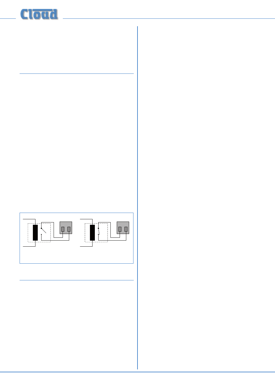
when making the connection. The CX261 will mute on
either a contact closure at the Music Mute input (NO) or
an open circuit (NC). Selection of NO or NC operation is
made with internal jumper J9. NO is the factory default. See
page 15 for details of jumper location. The diagram below
shows the two connections.
1
2
MUSIC MUTE
INPUT
RELAY
NORMALLY OPEN (NO)
CONNECTION
1
2
MUSIC MUTE
INPUT
RELAY
NORMALLY CLOSED (NC)
CONNECTION
fig.11: Remote music mute terminations
Bose® Equalisation Modules
The CX261 is compatible with single channel Bose®
Series II equalisation modules. EQ modules are available to
suit the following Bose® loudspeakers:
•
Panaray® MA12
•
Panaray® 402-II, 502B and 502BEX
•
Panaray® LT Series:
Models 3302, 4402, 9402 and 9702.
Modules to suit other models are available – please enquire.
Installation Instructions
Refer to the PCB layout diagram (see page 15) for the
location of the Bose® EQ module connectors. Note that
there are two connectors, one per main output (LEFT and
RIGHT). There is no provision for fitting an equalisation
module to the auxiliary/MOH output.
To install an EQ module, proceed as follows:
•
Isolate the unit from the mains.
•
Remove the top panel.
•
Plug the Bose® equalisation module onto its connector;
note that the connector has two notches on one
side which engage with lugs on the module’s mating
connector to ensure correct orientation.
•
Replace the top panel.