2 general description, 3 schematic diagram 4 music inputs – Cloud Electronics CX133 User Manual
Page 3
2
CX133: I
NSTALLATION AND OPERATION MANUAL
1 Safety
Notes
• Do not expose the unit to water or moisture
• Do not expose the unit to naked flames.
• Do not block or restrict any air vent
• Do not operate the unit in ambient temperatures above 35
o
C
• Do not perform any internal adjustments unless you are qualified to do so and fully
understand the hazards associated with mains operated equipment.
• The unit has no user serviceable parts. Refer any servicing to qualified service
personnel.
• If the moulded plug is cut off the lead for any reason, the discarded plug is a
potential hazard and should be disposed of in a responsible manner.
For more detailed information refer to the rear of the manual.
2 General
Description
The Cloud CX133 is versatile audio mixer with applications in Licensed, Retail and Leisure
venues. The unit has facilities for three stereo line signals and one microphone signal that
can be fed, in stereo, to two areas, each with a front panel mounted music source select
switch and adjacent music level and microphone level controls. In addition, a fixed level
‘Utility’ output is provided to serve general utility areas such as toilets and foyers etc. All pre-
set controls are located on the rear panel with additional configuration jumpers mounted on
the printed circuit board. Remote level controls can be wired to the two stereo zones for
applications that require remote control of the music level.
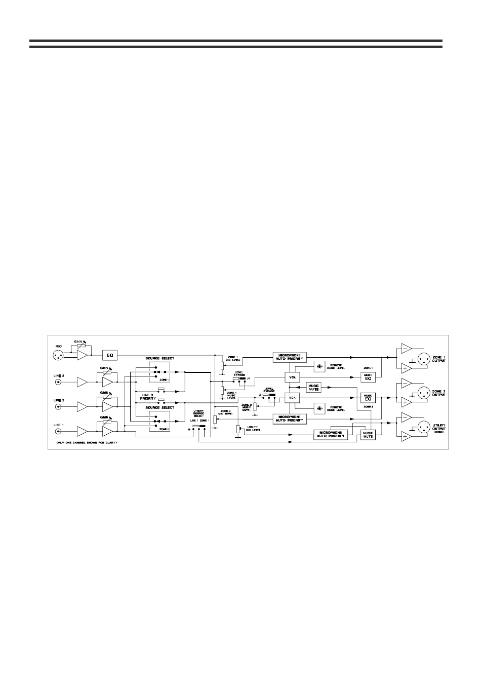
3 Schematic
diagram
4 Music
Inputs
The unit has three stereo line inputs; these are suitable for most music sources such as
compact disc players, tape players, satellite receivers and the like. All inputs are unbalanced
and use RCA phono sockets. The input impedance is 47k ohms. The Line 3 input can be
configured to have priority over any other music source, see section 6.
4.1
Sensitivity & Gain Control
All three stereo line inputs have a pre-set gain control on the rear panel adjacent to the
respective input socket. The gain control has a range of 20dB allowing the input sensitivity to
be varied from -12dBu (200mV) to +8dBu (2.0V). The pre-set gain control should be set so
that all the input signals are operating at the same level and that the front panel level control
has an optimum range of control.
29/05/02 V9