7 microphone input, 8front panel level controls, 9 microphone equalisation – Cloud Electronics CX133 User Manual
Page 6: 10 microphone priority, 01 microphone input, 02 gain control
CX133: I
NSTALLATION AND OPERATION MANUAL
5
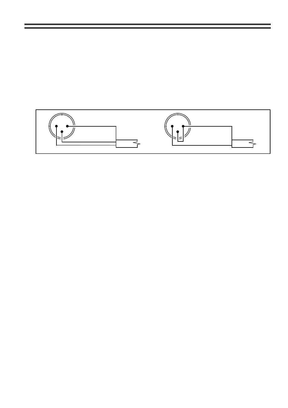
7 Microphone
Input
7.01 Microphone
Input
A microphone input is provided and the microphone amplifier is an electronically balanced,
transformerless design configured for optimum low noise performance. The input impedance
is greater than 2k
Ω and is suitable for microphones in the 200 to 600 ohm range. Input is via
a gold plated 3-pin XLR type connector with latch, which is positioned on the rear panel. For
balanced microphones, connect the cable screen to pin 1, the in phase signal to pin 2 and
the reverse phase to pin 3. To operate the channel in the unbalanced mode, connect pin 3
to pin 1 (ground) inside the XLR cable plug. Use pin 2 as hot and pin 1 as screen (ground)
Figure 6
BALANCED
GROUND (SCREEN)
REV - PHASE (-)
IN - PHASE (+)
MIC INPUT
TERMINATION
1
2
3
1
2
3
LINK PIN 3 TO PIN 1
HOT (+)
UNBALANCED
GROUND (SCREEN)
7.02 Gain
Control
A pre-set gain control is provided adjacent to the XLR input connector. The gain can be
adjusted from 0dB to 60dB and this wide range of gain allows direct connection of high
output devices such as radio microphones without the need for additional attenuation. A high
overload margin is maintained at all gain settings.
8
Front Panel Level Controls.
A separate microphone level control is provided for both Zone 1 and Zone 2 and these
provide the user with a convenient means to operate the microphone at a suitable level in
the zone of their choice. The microphone signal is routed directly to the respective output
stage and is unaffected by the operation of the music level control. The gain control on the
rear panel should be set at a level where it is not possible to have excessive gain even when
the front panel level controls are fully clockwise. Self adhesive labels are provided to
customise the controls.
9 Microphone
Equalisation
The microphone channel has both a fixed high pass filter and independent pre-set
equalisation controls positioned on the rear panel. The filter attenuates the signal below
100Hz and the tone controls provide
±10dB at 100Hz and 5kHz.
10 Microphone
Priority
Fully automatic, voice operated priority is provided for the microphone channel. A priority
on/off switch is positioned on the rear panel. With the priority function switched on, when a
microphone signal is detected, the music signal is attenuated, allowing the message to be
clearly heard; normal music operation is restored smoothly after the announcement has
been made. Once switched on, the mic priority will operate on Zone 1, Zone 2 & the Utility
Output.
11
Inhibiting mic or music sections
If the CX133 is required to provide a microphone signal, without any music programme, the
mixer can be configured to operate with the music channel disabled by simply removing the
two resistors R72 & R162 for zone 1 and R54 & R55 for zone 2. If there is a requirement to
operate either zone with the microphone channel disabled, remove R68 & R138 for zone 1
and R50 & R164 for zone 2.
29/05/02 V9