12 zone outputs, 13 utility output, 1 music equalisation – Cloud Electronics CX133 User Manual
Page 7
6
CX133: I
NSTALLATION AND OPERATION MANUAL
12 Zone
Outputs
The two stereo output zones have balanced output stages using 3 pin XLR type connectors
and can operate into loads as low as 600
Ω. The nominal output level is 0dBu (775mV) but
the CX133 can operate with a wide range of signal levels up to a maximum output of +20dBu
(7.75V). A 3-pin XLR type female connector is required for each output.
OUTPUT
TERMINATION
BALANCED
UNBALANCED
HOT (+)
GROUND (SCREEN)
1
3
2
NO CONNECTION TO PIN 3
GROUND (SCREEN)
REV - PHASE (-)
IN - PHASE (+)
1
2
3
Figure 7
For balanced interconnections, 2-core screened cable should be used. Connect the cable
screen to pin 1. Pin 2 is the in phase signal (normally red) and pin 3 is the reverse phase
signal (normally blue or black). If you plan to connect any zone output to an unbalanced
load, see section 15.4 'Unbalanced Mode'. Full connection details are printed on the
underside of the CX133.
12.1 Music
Equalisation
Both Zone 1 and Zone 2 have separate pre-set treble and bass controls for the music signals
only. These pre-set controls are located on the rear panel adjacent to the respective zone
output sockets. The music treble control has a range of
±10dB at 10kHz and the music bass
control operates with a range of
±10dB at 50Hz.
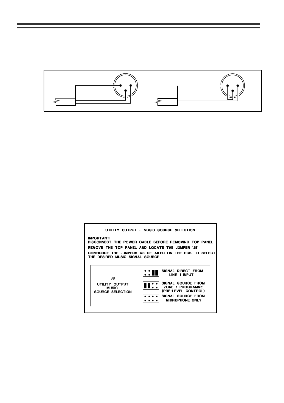
13 Utility
Output
The CX133 is fitted with a fixed level, balanced output primarily intended to provide a mono
signal for utility areas such as toilets and foyers where it is desirable to feed a music + mic
programme at a constant level, totally independent of the variable programmes of Zone 1&2.
Figure 8
The utility output has a choice of three input sources, selected by a PCB mounted jumper.
The CX133 leaves the factory configured to provide a music signal derived from the Zone 1
music source selector (pre-level control). Alternatively, the jumper J8 can be set to source
the music signal directly from the Line 1 input (see Figure 8). A pre-set microphone level
control, positioned adjacent to the output socket can be set to provide microphone signals at
the optimum level; if the priority function is switched on, the music signals will attenuate
when an announcement is made. If the music source jumpers are removed, the output can
be used as a microphone only signal to serve areas requiring music free announcements.
29/05/02 V9