14 music mute (fire alarm interface), 1 multi-zone applications, 2 emc considerations – Cloud Electronics CX133 User Manual
Page 8: 3 earthing
CX133: I
NSTALLATION AND OPERATION MANUAL
7
14
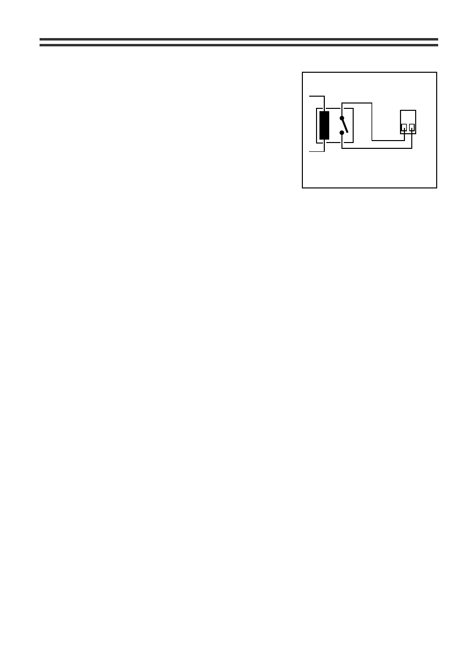
Music Mute (Fire Alarm Interface)
In certain installations, such as licensed premises or
retail outlets within a shopping mall, there may be a
local authority or fire service requirement to mute the
music signals via a fire alarm control panel in an alarm
condition. The CX133 provides a facility to mute the
music signals only, by using a fully isolated pair of
contacts (usually a relay mounted close to the CX133
which is powered by the fire alarm control panel)
which should close during an alarm condition (the
installation of this relay is normally undertaken by the
fire alarm installation company). The front panel
mounted 'Music Mute' LED will illuminate to indicate
the operation of the mute circuit.
1
2
RELAY
CX133
2 POLE
CONNECTOR
THE RELAY CONTACT MUST BE VOLTAGE
FREE AND FULLY FLOATING
REMOTE MUSIC MUTE TERMINATIONS
Figure 9
15 General
Notes
15.1 Multi-zone
Applications
Where the sound system specification calls for separate control in more than 2 zones, the
CX133 can be used in multiples. The signal sources can be connected to several inputs as
required but care must be taken to ensure that the output stage of the signal source is
capable of driving a lower impedance load. The impedance of the line input stage is 47k
Ω
and it would be reasonable to assume that most op-amp based signal sources should drive a
10k
Ω load, thus allowing up to five parallel circuits. The input impedance of the microphone
amplifier is 2.4k
Ω making it suitable for a microphone with a maximum impedance of 600Ω.
A single 200
Ω microphone could therefore be connected to three balanced inputs. To avoid
any problems associated with differences in mains supply earthing, we recommend that all
the CX133's used in a multi-zone application should be located close together and
connected to a common mains supply.
15.2 EMC
Considerations
The CX133 fully conforms to the relevant electromagnetic compatibility (EMC) standards and
is technically well behaved; you should experience no problems interfacing the unit to other
items of equipment and under normal circumstances no special precautions need to be
taken. If the unit is to be used within close proximity to potential sources of HF disturbance
such as high power communication transmitters, radar stations and the like, it is suggested
that the cable screen be connected to the shell of the XLR type connector and the line input
signal leads be kept as short as possible. Always use balanced interconnections wherever
possible. If the CX133 is mounted in a 19” rack, do not locate the unit in close proximity to a
powerful amplifier, which may radiate a strong magnetic field from the power transformer.
15.3 Earthing
The 0V rail of the CX133 is coupled to the chassis ground by a parallel resistor/capacitor
network and no interconnection problems should be encountered. When several mains
powered units are connected together via their signal cables, there is a risk of one or more
earth loops which may cause an audible hum on the system even with the gain controls set
to minimum. The 'hum' can be remedied in several ways; the preferred method is to operate
the output links to the power amplifiers in the balanced mode, with the cable screen only
connected at the receiving end (amplifier input). The signal source units should be located as
close as possible to the CX133 and the metal housing of the various units should not be
electrically connected together through the equipment rack. If this is a problem, rack isolating
kits are available from specialist hardware suppliers. If the problem persists, try to connect all
the interconnected units, including the power amplifiers to a common power source to
ensure that a common ground is provided.
29/05/02 V9