Cb 2 series, 3af / at switch, Ip5000 connector side – Code Blue CB 2-E ECONOMICAL WALL MOUNT HELP POINT User Manual
Page 32
Code Blue
•
259 Hedcor Street
•
Holland, MI 49423 USA
•
800.205.7186
•
www.codeblue.com
GU-149-G
page 32 of 43
CB 2 Series
Administrator Guide
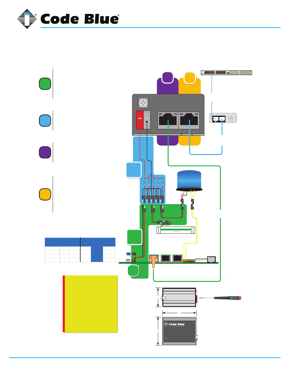
19 PoE Installation Instructions
ED Image page
2
802.3af / at Switch
LAN 2
LAN 1
WAN
PoE
PAS
Control
Aux ports
PAS
Audio
+ -
+ -
Power | Battery
S-550
S1000
E
th
ern
et
1
IP5000 Connector Side
Grounding:
Should a ground be needed,
there’s a ground screw on the
enclosure with grounding logo
next to it.
When the splitter is mounted to
the mounting bracket the bracket
becomes the ground to the
chassis of the enclosure,
however local codes may require
a ground wire be attached to the
screw in order to comply.
4
3
Data +PoE
DATA
1b
LED Faceplate Light Bar
12VDC
PoE
CB14591 PoE Splitter
2.6
2.1
1.3
1
First, Electrical connection: All 3
Code Blue device’s should to be
connected to the 5 place manifold
Special Note: Notice the power cable is
connected to the Battery / Alternative Power
port of the IP5000. – See Item 1b
2
Second: Manifolds fused red lead
and black wires are secured to
spring cage connector on the
CB14591. SEE DIAGRAM
Third Step: Connect the DATA
cable RJ-45 from the Splitter
“DATA” to the IP5000 WAN PoE
port.
3
4
Fourth Step: Plug in the Ethernet
PoE Cat 5e Cable to Data+PoE
Input jack on the Splitters.
Upon PoE Negotiation with the
PoE switch port, power will be
granted to the Splitter, and the
indicator along with the device
attached will turn on.
Item
InRush
(i)
InRush
Wattage Norm (i)
802.3af
Wattage
802.3at
Wattage
IP5000
0.22
2.64
0.09
1.08
1.08
FP LED
0.08
0.96
0.04
0.48
0.48
Combo LED
0.3
3.6
0.26
3.12
3.12
Totals
0.6
7.20
0.39
4.68
4.68
CAT5e
< 3ft
in out
GRD
3ft
Cat5e
Cust
Cat5e