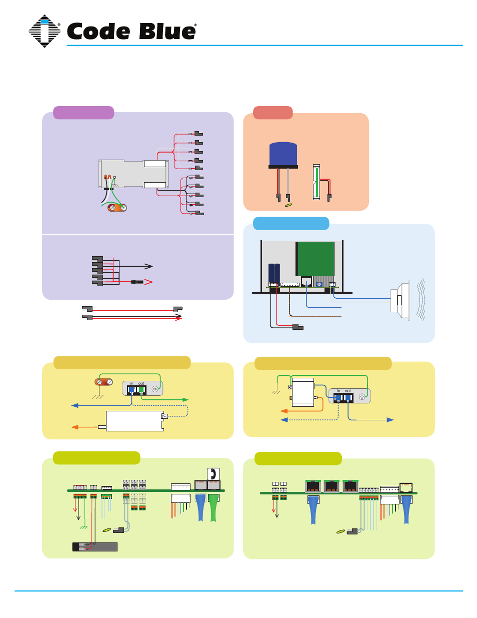
Cb 2 series, Administrator guide, 21 cb 2-e wiring diagram – Code Blue CB 2-E ECONOMICAL WALL MOUNT HELP POINT User Manual
Page 34
Code Blue
•
259 Hedcor Street
•
Holland, MI 49423 USA
•
800.205.7186
•
www.codeblue.com
GU-149-G
page 34 of 43
CB 2 Series
Administrator Guide
POWER SUPPLY
CB 2-E SPEAKER/AMP
IA4100 COMMUNICATION CONNECTIONS
RJ-11 cord
Fiber to FXS
(ATA) Converter
Fiber
11751
POTS line
Cat 5e or 6
LIGHTING
1
+ - + -
1
+
-
IA4100 SPEAKERPHONE
IP5000 SPEAKERPHONE
PAS
CONTROL
PAS
AUDIO
AUX
PORTS
LAN PoE
LAN 1
LAN 2
PAS
CONTROL
PAS
AUDIO
NOTE: Use the supplied modular inter-connects to
link the unit’s various powered devices.
• Multi-Tap LV fuses are
generally 2A GMA
AUDIO
OUTPUT
120V, 240V, 277V,
347V AC @ 250V A
Aux
In-
put 2
Aux
Input
1
12V DC
24V AC
Chassis
Ground
12-24V AC or DC
OUTPUT
1 2 3
N.O.
N.C.
G
-
+
-
+
3
1
2
4
BATT
ACC
POWER
AUX
INPUTS
12-24V
AC or DC
standard
BATT
PWR
Aux
Out-
put 1
Battery 12V @ 2.0Ahr
Aux
Out-
put 2
Aux
Input
1
Battery 12V @ 2.0Ahr
POWER MANIFOLD
MULTI-TAP
RJ-11 cord
Fiber to FXS
(ATA) Converter
Fiber
11751
Fiber
POTS line
GRD
GRD
Common or Neg
PAS Audio
PAS Control
PAS Gen2 Amp
24V AC @ 3 Amps
12-24V
AC or DC
standard
LED
Faceplate
Light
12-24V AC
or DC
Beacon/Strobe
12-24V AC or DC
Phone
Line
Audio
Output
phone specific
Product wiring diagram shown reasonably represents current offering and is intended to assist in component identification and service. Earlier product
production may have different components and wiring connections. Reference the model and serial number from the unit ID tag and contact
manufacturer to confirm replacement part version and availability.
IP5000 COMMUNICATION CONNECTIONS
Copper Cat 6
Ethernet Surge
Protector
One pair modular
Fiber
Converter
21 CB 2-e Wiring Diagram