3 terminal default conditions, 4 theory of operation, 1 remote interface specification – Comtech EF Data CST-5005 User Manual
Page 74
Theory of Operation
CST-5005 C-Band Satellite Terminal
5–4
Rev. 1
5.1.2.1 Remote Interface Specification
Refer to Appendix A.
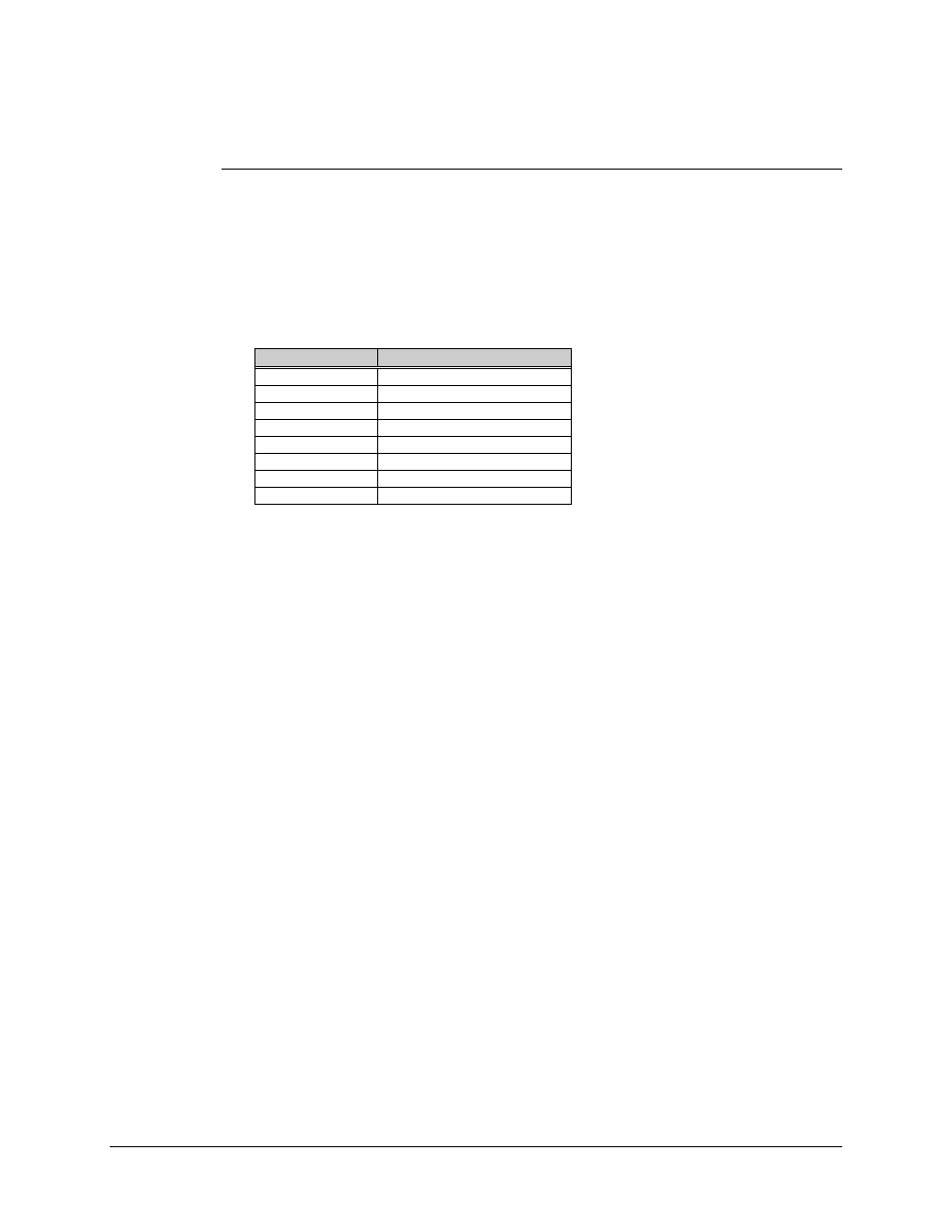
5.1.3 Terminal Default Conditions
On initial power-up, the unit will default to the following parameters:
Parameter
Default
Baud Rate
9600
Parity
Even
Device Address
1
U/C Gain
Max gain/or min attenuation
D/C Gain
Max gain/or min attenuation
RF Output
OFF
U/C Frequency
6135.00 MHz
D/C Frequency
3925.00 MHz
5.1.4 Theory of Operation
Refer to Figure 5-3 for a functional block diagram of the M&C.
The M&C board performs the following operations:
•
Receives the desired frequency from either the remote RS-232-C/485 or KP-10
keypad, and after converting it to a synthesizer setting, stores it to the applicable
synthesizer output latch.
•
Reads the thermistors located in the up converter, down converter, and high-
power amplifier, and converts them to temperatures for display.
•
Reads the characterization EEPROMs in the up converter, down converter, and
high-power amplifier, and calculates an Automatic Gain Control (AGC) voltage
based on frequency and temperature to linearize the respective module.
•
Receives fault inputs from all modules, and presents them to the remote
RS-232-C/485 and the optional KP-10 keypad display.
•
Performs an initial current sense on the LNA, and stores the reading in
EEPROM. Subsequent current sense readings are taken and compared to the
initial reading to determine a fault.