3 “sspa sw out | j5” connector – Comtech EF Data PCB-4000 User Manual
Page 25
PCB-4000 1+1 Phase Combiner
Revision 2
External Connectors
MN/PCB4000.IOM
2–5
2.2.3
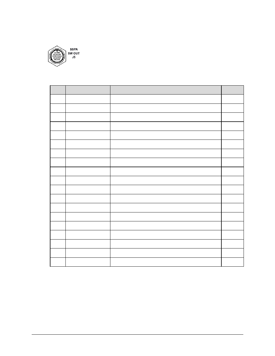
“SSPA SW OUT | J5” Connector
The 19‐pin circular “SSPA SW OUT | J5” connector, type MS3112E14‐19S,
connects via a “Y” cable to the SSPA #1 and SSPA #2 waveguide switches.
Mating connector: ITT Cannon MS3116J14‐19P (CEFD P/N CN/MS3116J14‐19P)
Table 2-4. “SSPA SW OUT | J5” Pinouts
Pin # Signal Function
Signal Name / Description
Direction
A
Pos1, SW1 Drive
Output
B
Ground GND
C
POS2, SW1, Drive
Output
D
POS1, SW1, Indicator
Input
E
Ground GND
F
POS2, SW1, Indicator
Input
G
NC
H
POS1, SW2, Drive
Output
J
Ground GND
K
POS2, SW2, Drive
Output
L
POS1, SW2, Indicator
Input
M
Ground GND
N
POS2, SW2, Indicator
Input
P
NC
R
NC
S
NC
T
NC
U
NC
V
NC