Cybex 425A Arc Trainer User Manual
Page 52
Cybex Arc Trainer 425A Owner’s Manual
CAUTION: A minimum of two people are required to lift, move and assemble the unit. Always
use proper lifting methods when moving heavy items.
4. Lift and move the unit
A.
Carefully remove lag bolts and shipping supports.
NOTE:
B.
At least two people should lift and move or roll the unit to the location where you intend to
leave it. Use proper lifting methods.
NOTE: If installing the Personal Entertainment Monitor
refer to page 5-12 for installation instructions.
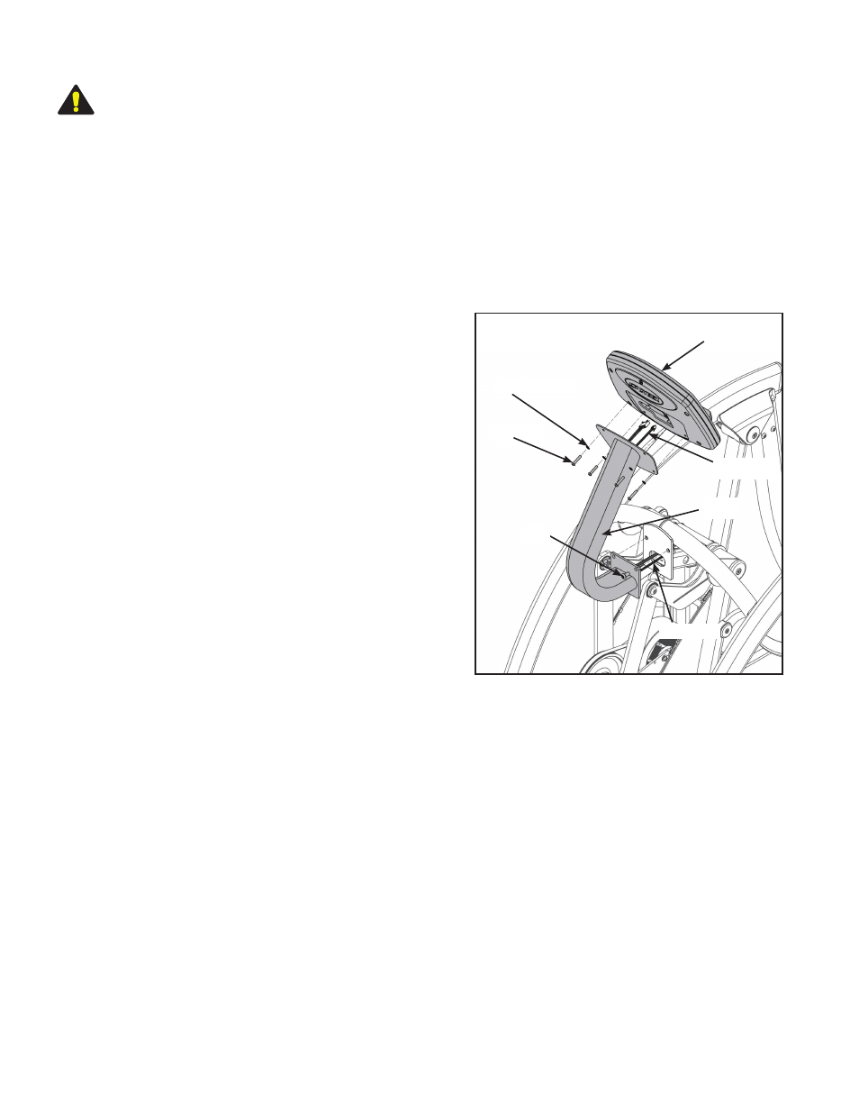
5. Install cables in console support bracket.
A. Locate the console support bracket (#12).
B. Locate the console and heart rate cables on the
mainframe assembly.
C. Insert the cables into the bottom of the console
support bracket (#12) until they exit the top.
6. Attach the console support bracket.
A. Locate the console support bracket (#12) and
three BHSCS .375-16 x .75 (#19).
B. Position the console support bracket (#12) on
the main frame assembly and hand thread each
of the three BHCS .375-16 X .75. (#19) See
Figure 4.
C. Securely fasten the .375-16 x .75 (#19) with
the 7/32” Allen wrench (#27) provided.
7. Attach the console assembly.
A. Locate console assembly (#2) and four BHSCS .250-20 x 1.250 (#21) and four lock washers (#22).
B. Connect the console and heart rate cables exiting top of the console support bracket (#12) to the
console (#2). See Figure 4.
C. Position console assembly (#2) and hand thread each of the four BHCS .250-20 (#21) with four lock
washers (#22). See Figure 4.
NOTE: Verify cables are not pinched.
D. Using the 5/32” Allen wrench (#26) provided, secure the console (#2) to the console support bracket
(#12) with the four lock washers (#22) and four BHSCS .250 x 1.250 (#21).
Figure 4
#2
#22
#21
Cables
#19
#12
Cables
Setup
and Assembly
Page 5-6