Chapter 2 – DFI SB332-C User Manual
Page 21
www.dfi .com
21
Chapter 2 Hardware Installation
Chapter 2
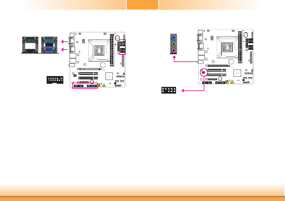
COM (Serial) Ports
COM 1
The pin function of COM 1 port will vary according to JP1’s setting. Refer to “COM1 RS232/
RS422/RS485 Select” in this chapter for more information.
The serial ports are asynchronous communication ports with 16C550A-compatible UARTs that
can be used with modems, serial printers, remote display terminals, and other serial devices.
Connecting External Serial Ports
Your COM port may come mounted on a card-edge bracket. Install the card-edge bracket to
an available slot at the rear of the system chassis then insert the serial port cable to the COM
connector. Make sure the colored stripe on the ribbon cable is aligned with pin 1 of the COM
connector.
BIOS Setting
Configure the serial ports in the Advanced menu (“Super IO Configuration” submenu) of the
BIOS. Refer to chapter 3 for more information.
COM 1:
RS232/422/485
COM 2
Audio
Rear Audio
The system board is equipped with 3 audio jacks. A jack is a one-hole connecting interface for
inserting a plug.
• Mic-in Jack (Pink)
This jack is used to connect an external microphone.
• Line-in Jack (Light Blue)
This jack is used to connect any audio devices such as Hi-fi set, CD player, tape player,
AM/FM radio tuner, synthesizer, etc.
• Line-out Jack (Lime)
This jack is used to connect a headphone or external speakers.
Front Audio
The front audio connector allows you to connect to the second line-out and mic-in jacks that
are at the front panel of your system.
Line-out
Line-in
Mic-in
Rear audio
Front audio
1
Mic2-L
Line2-R
Front_IO_Sense
GND
Presence Signal
Ke
y
2
10
Mic2-
JD
Line2-
JD
9
Mic2-R
Line2-L
COM 2-COM 10:
RS232
COM 3 COM 4 COM 5 COM 6
COM 10 COM 9
COM 8 COM 7