Cable connection, Indicator connection diagram, Bottom panel cable connections – Digi-Star EZ400 User Manual
Page 25
Advertising
Installation
D3655-US Rev E
EZ400 User’s Manual
21
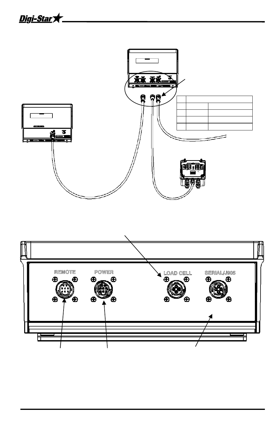
Cable Connection
Indicator Connection Diagram
Bottom Panel Cable Connections
Scale Indicator
Remote Indicator
(Optional)
See J-Box
Connections
Power Cord
J-Box Connection
Serial/J905
(Optional)
Remote Port
(Optional)
Power Cord
Connection
Pin To 12VDC Power Supply
1 Red +Terminal
2 Black -Terminal
3 Orange Alarm Out
4 Blue Remote Input
Advertising
See also other documents in the category Digi-Star Equipment:
- ERM-2.4 (11 pages)
- Analog Output EZIII (8 pages)
- ICP 300 (14 pages)
- DataLink (11 pages)
- DataLink (39 pages)
- Cab Control 2.4 (10 pages)
- RD 4000 (4 pages)
- RD 440 (4 pages)
- RD 2500 (5 pages)
- SLC 2400 (22 pages)
- RD 2400 (4 pages)
- Cab Control 400 (9 pages)
- DataKey Docking Station USB Drivers (2 pages)
- Data Downloader (DDL) (3 pages)
- EZ2400 (29 pages)
- EZ2500 (26 pages)
- EZ3400VL (33 pages)
- EZ 3600 Manual DataKey (50 pages)
- EZ3400(V) (40 pages)
- EZ3400(V) (43 pages)
- EZ 3500 Operators Manual (22 pages)
- EZ 3600 USB Manual (52 pages)
- GT400 (26 pages)
- EZ 4600 Manual DataKey (51 pages)
- EZ 4600 Manual USB (53 pages)
- GT460 (48 pages)
- NT 460 (45 pages)
- GT465 (39 pages)
- SW2600EID (46 pages)
- SW300 (17 pages)
- Stockweigh 300 (23 pages)
- ST 3400 (46 pages)
- SW600 (24 pages)
- StockWeigh 550 EID (38 pages)
- SW4600EID (45 pages)
- CC400 (9 pages)
- TST7600 with TMR Tracker (51 pages)
- AGCO - White 8531 (14 pages)
- Case IH 1260 – 32/36 (12 pages)
- Case IH 1260 – 32/36 (12 pages)
- Case IH 1250 - 12/16/24 (18 pages)
- Diet Manager Set-up & User Guide (17 pages)
- Downloader Module (7 pages)
- Diet Manager Full Guide (28 pages)