DR Power 11.5 FPT User Manual
Page 16
16
DR
®
CHIPPER/SHREDDER
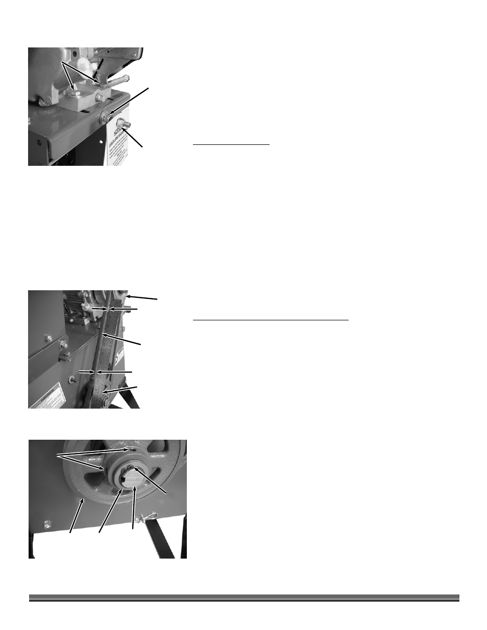
5. Loosen the four Engine Bolts using two 1/2" Wrenches (Figure 16).
6. Using a 1/2" Wrench, turn the Tag Nut away from the Adjust Nut.
7. Turn the Adjust Nut in against the Frame to tighten (if Belt is too loose) or
out to loosen (if Belt is too tight) for the correct Belt tension.
8. When the Belt is at the proper tension tighten the Engine Hardware.
9. Screw the Tag Nut up to the Adjust Nut.
10. Replace the Baffle Plate and Belt Guard.
REPLACING THE BELT
Tools and Supplies Needed:
Two 1/2" Wrenches
1. Follow the disassembly steps in the previous “Checking and Setting Belt
Tension” section (steps 1 and 4 through 6).
2. Loosen the Adjust Nut to move the Engine forward until the Belt can be
removed.
3. Install the new Belt onto the Clutch and Rotor Pulley. Turn the Adjust nut
against the Frame to tighten the Belt and follow the steps that apply in the
“Checking and Setting Belt Tension” section to set Belt tension (steps 2, 3
and 7).
4. When the Belt is at the proper tension tighten the Engine Hardware.
5. Screw the Tag Nut up to the Adjust Nut.
6. Replace the Baffle Plate and Belt Guard.
CHECKING AND SETTING BELT ALIGNMENT
Tools and Supplies Needed:
1/2" Wrench
Straight Edge
5/32" Allen Wrench, Snap Ring Pliers and Loctite
®
243*
*(if alignment is needed)
1. Remove the Belt Guard by following step 1 of the “Checking and Setting Belt
Tension” section.
2. Place one end of a Straight Edge across the face of the Rotor Pulley and the
other end near (but not touching) the Clutch (Figure 17).
3. The Straight Edge should be parallel with the Belt. If the gap between the
top portion of the Straight Edge to the Belt is equal to the gap between the
bottom portion of the Straight Edge to the Belt, no adjustment is needed
(continue at step 4). If the gaps are not equal, adjustment is needed
(continue to the following step “a”):
a)
Write down the difference in the gaps to use for adjustment.
b)
Remove the Belt from the Rotor Pulley by following the steps as described
in the previous “Checking and Setting Belt Tension” section (steps 4
through 7).
c)
Remove the two Set Screws with a 5/32" Allen Wrench (Figure 18).
d)
Remove the Retaining Ring with the Retaining Ring Pliers
e)
Remove the Shims and Rotor Pulley from the shaft.
Retaining
Ring
Figure 18
Shims
Rotor
Pulley
Rotor
Shaft
Set
Screws
Belt
Straightedge
On side face of
Rotor Pulley
Figure 17
Clutch
Gap
Gap
Adjust Nut
Figure 16
Tag Nut
Engine
Hardware