Removing and replacing the clutch – DR Power 11.5 FPT User Manual
Page 20
20
DR
®
CHIPPER/SHREDDER
Removing and Replacing the Clutch
The design of the Clutch on your machine is for rugged, dependable service, however, it is important to understand the limitations
of a Clutch. The Clutch design is to provide load free starting of the Engine, and slippage under excessive overloading of the
driven application. These features help protect the Engine from damages such as broken crankshafts and starters. The Clutch on
this machine is permanently lubricated and does not require oil or grease. The Drum, Shoes, and Springs in the Clutch are
normal wear items. If, after long periods of use, the Drum wobbles excessively, or if you notice decreased performance of the
Clutch, replace the Clutch.
The Clutch obtains its power from the Engine RPM. The lower the engagement speed, and the higher the maintained Engine
speed, the more torque the Clutch can transfer to the driven unit. NEVER operate the DR CHIPPER/SHREDDER Engine at less
than full RPM.
Tools and Supplies Needed:
Two 1/2" Wrenches
9/16" Wrench
Anti-seize compound
1. Remove the Belt as described in the “Replacing The Belt” section.
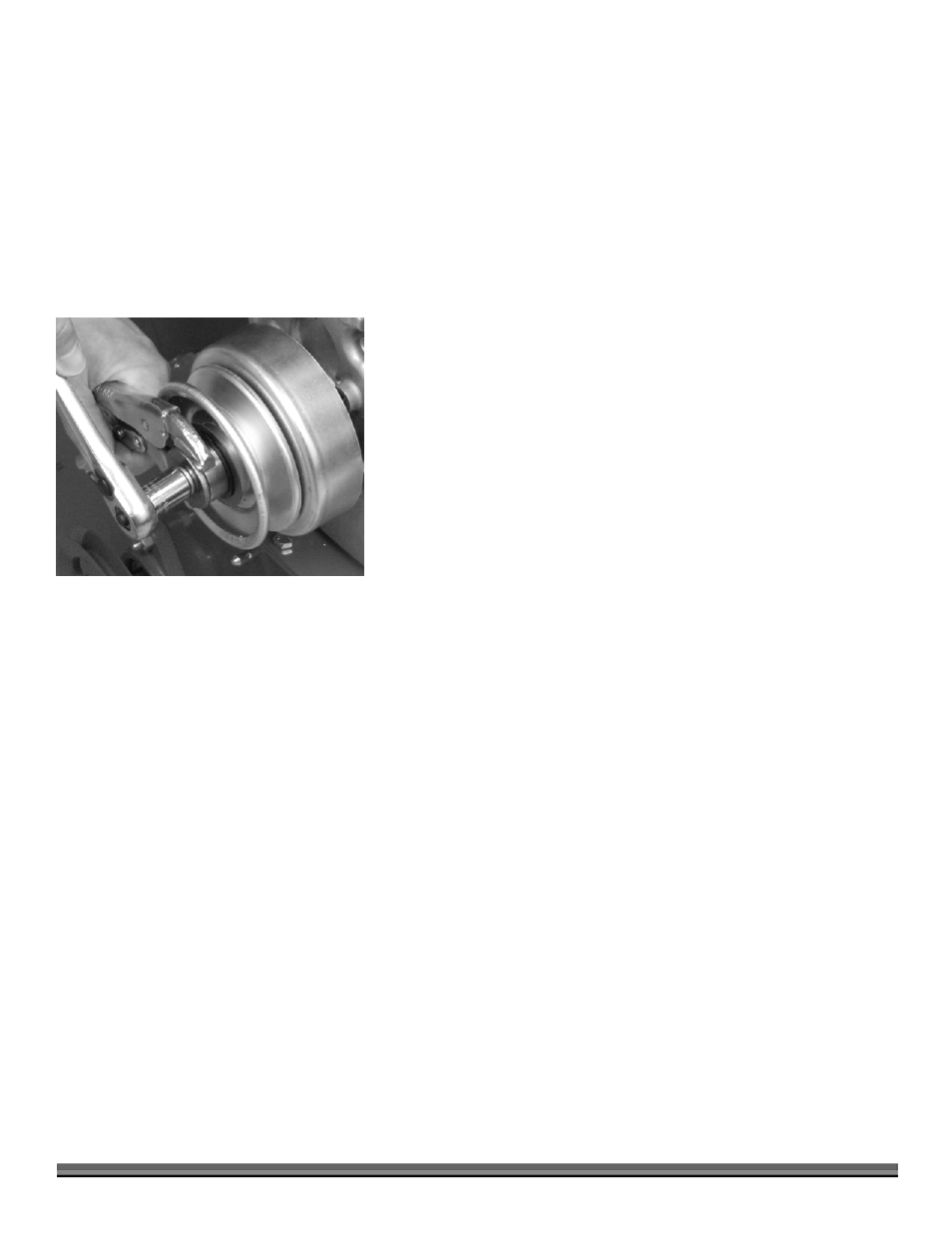
2. Remove the Clutch from the Engine Crankshaft by removing the Clutch Bolt
and Washer and then slide the Clutch Assembly from the Crankshaft (Figure
28) (any Spacers remain on the Crankshaft).
Tip: Hold the Hub with Vise Grips while loosening the Clutch Bolt.
3. Remove the Key from the Keyway in the Engine Crankshaft and set it aside.
4. Clean the Engine Crankshaft and remove any burrs, then apply anti-seize
compound to the Crankshaft.
5. Install the Key in the Keyway of the Engine Crankshaft, align the Key with the
slot in the new Clutch Hub, and then slide the new Clutch Assembly onto the
Crankshaft followed by the Washer and Clutch Bolt. Tighten the Bolt
securely.
6. Reinstall the Drive Belt and set the Belt tension as described in the
“Checking and Setting Belt Tension” section.
7. Reinstall the Belt Guard and Baffle Plate.
Figure 28