Specifications, Assembling the mower, Installing the handlebars – DR Power Lawn Mower Subaru Engine (January 2013 - March 2014) User Manual
Page 8
8
DR
®
SP22 MOWER
Specifications
Engine
See Engine Manufacturers Manual
for detailed Engine information
Cutting Width
560mm (22 inch)
Cutting Height
9 Heights, 1" to 3.4"
Deck Material
Cast Aluminum
Wheel Size
8" x 1.75" Front, 9" x 1.75" Rear
Dimensions
63" L x 24" W x 43" H
Weight
108 lbs.
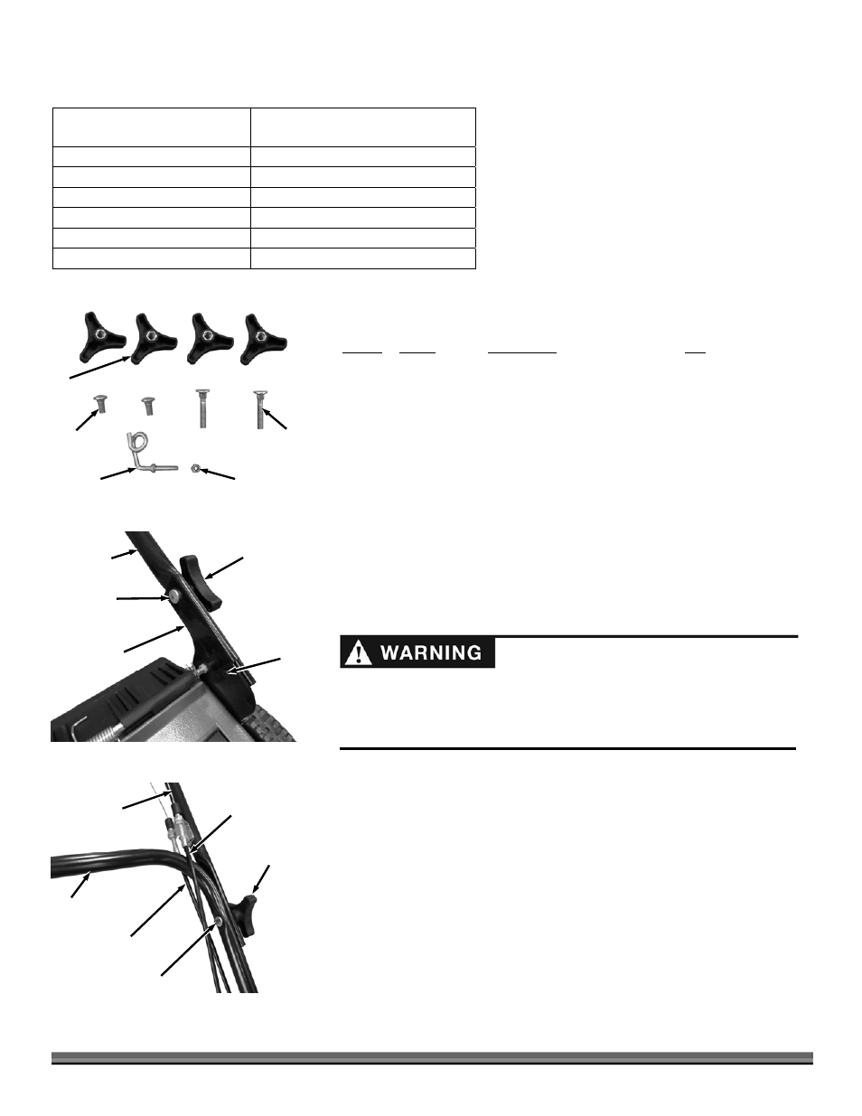
Parts Supplied in Shipping Box:
* = Hardware Package (Figure 2)
Item # Part
# Description
Qty
1* ........... 32257 .............. Knob, Handlebar ............................ 4
2* ........... 32256 .............. Bolt, Carriage, Short ....................... 2
3* ........... 32296 .............. Bolt, Carriage, Long ....................... 2
4* ........... 32530 .............. Nut, Nylon Lock M6 ....................... 2
5* ........... 32293 .............. Guide, Pull Start ............................. 1
6 ............. 32368 .............. Mulching Plug ................................ 1
7 ............. 32290 .............. Lower Handlebar ............................ 1
8 ............. ........................ Upper Handlebar Assembly ........... 1
Compare the contents of the Shipping Box with the “Parts Supplied” list above.
If you have any questions please contact us at www.DRpower.com or call 1-800-
DR-OWNER (376-9637) for assistance.
Assembling the Mower
Tools Needed:
10mm Wrench
Installing the Handlebars
1. Insert the pins of the Lower Handlebar into the holes of Handlebar Brackets
(Figure 3). Insert the short Carriage Bolts through the Lower Handlebar and
Brackets. Install and tighten the Lower Handlebar Knobs onto the Carriage
Bolts as tight as you can by hand.
Note: make sure the Drive Cable goes under the Lower Handlebar for proper
clearance in the next step.
2. Carefully position the Upper Handle with Cables onto the Lower Handlebar
(Figure 4). Insert the long Carriage Bolts through the Upper and Lower
Handlebars. Install and tighten the Upper Handlebar Knobs onto the
Carriage Bolts as tight as you can by hand.
5
Figure 2
4
3
2
1
Folding or unfolding the handle improperly can damage the cables, causing
an unsafe operating condition.
Do not damage the cables when folding or unfolding the handle.
If a cable is damaged, contact us at www.DRpower.com.
Lower
Handlebar
Figure 3
Carriage
Bolt
Lower Handle
Knob
Handlebar
Bracket
Pin
Upper
Handlebar
Figure 4
Long Carriage Bolt
Upper
Handle Knob
Lower
Handlebar
Drive Cable
Engine Brake
Cable