Assembly – DR Power Redi-Plow Plus (Sept. 2013 - Present) User Manual
Page 6
6
DR
®
REDI-PLOW™ PLUS
Chapter 2: Setting Up The DR
®
REDI-PLOW™ PLUS
Assembly
Tools and Supplies needed:
Ft. lb. Torque Wrench
Impact or Ratchet with 9/16” and 3/4” Socket
Drill with 3/16” and 5/16” Drill Bit
#3 Phillips Driver Bit
Box Wrench 3/4”
Open Wrench 5/16”
Allen Wrench 3/16”
2 Short Pcs. of 2 X 4 Blocking
Bubble Level
Protective Eyewear
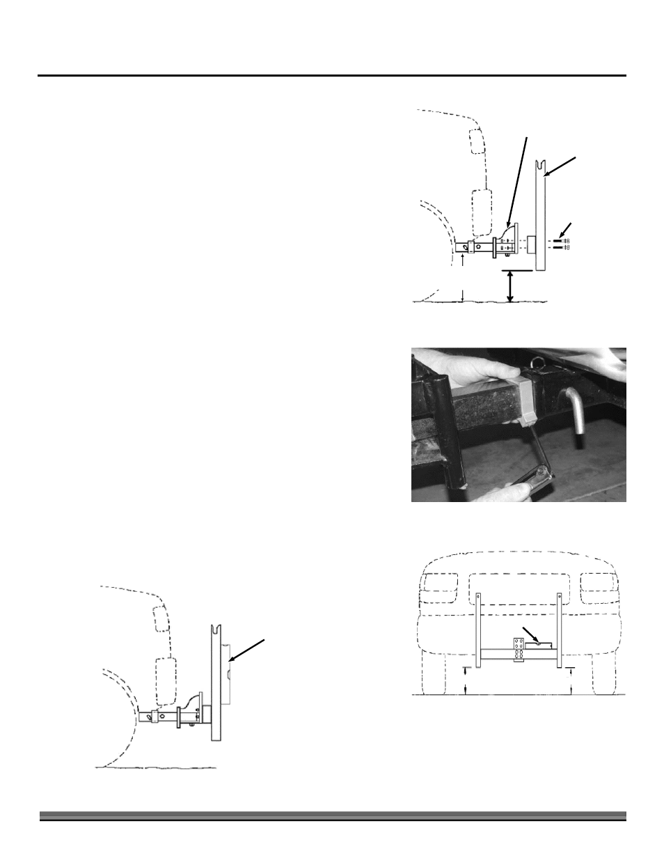
Note: Prior to plow assembly, park vehicle on level grade and install plow mount
receiver (shipped separately). Clearance under receiver should measure
between 8 to 16 inches above grade (Figure 1). Interceptor can be installed
with leg turned up or down as needed for proper push frame clearance
(Shown turned up in illustrations).
1. Insert interceptor into receiver – leg up. Secure with pins (interceptor has
choice of holes to allow for clearance when aligning blade). Hold push frame
against interceptor. Select 4 bolt hole pattern that positions push frame 8"
to 10" above grade. If lowest bolt pattern is too high, remove interceptor
and turn leg down. Bolt push frame (4 bolts 1/2" x 4" w/flat washers and
lock nuts) to proper hole height on interceptor – leave bolts snug tight for
now.
2. Push set collar tight against receiver – hold and tighten set screw with 3/16"
Allen wrench (Figure 2).
3. With bolts snug tight, level push frame horizontally (Figure 3).
4. Check push frame for vertical plumb (Figure 4). If plumb, tighten 4 bolts
now and go to step 5. If not plumb, refer to the following shim procedure.
Push Frame
Figure 1
Interceptor
4 Bolts 1/2" x 4",
8 Flat Washers,
4 Lock Nuts
Receiver Clearance
8" - 16"
Push Frame
Clearance 8" - 10"
Figure 2
8" - 10"
8" - 10"
Bubble Level
Figure 3
Bubble
Plumb
Figure 4