Usage of ex8000, 1 control modes, 1 e.d.i control mode – ESI EX8000 User Manual
Page 7: 2 standalone mode, 3 reset internal configuration, 2 audio routing, 1 audio routing mode selection
MaXiO XD
EX8000
3. Usage of EX8000
3.1 Control Modes
3.1.1 E.D.I Control Mode
When EX8000 is connected to the MaXiO PCI host card,
it is controlled via the E.D.I connection from the PC.
EX8000 automatically detects if it is connected to a PC
when power is switched on. In that case, it can only be
controlled via the MaXiO XD Control Panel software on
your PC. Check the MaXiO XD system manual for more
information.
3.1.2 Standalone Mode
When EX8000 is not connected to a MaXiO PCI host card, it works as a standalone device.
EX8000 automatically switches to this standalone mode when there is no active E.D.I signal when
power is switched on.
You can set up the internal audio routing and the system clock with the two clock selection buttons
(
) on the front panel.
11 12
3.1.3 Reset Internal Configuration
EX8000 will automatically keep the last configuration in standalone mode. If you want the reset this
value, press the first clock selection button (
) when all lights on the front panel are on during the
initialisation of EX8000 after power has been switched on.
11
The system clock will be set to the default (internal, 44.1 kHz); audio routing [MODE 1] will be
selected as default (see below).
3.2 Audio Routing
3.2.1 Audio Routing Mode selection
EX8000 has various digital and analog I/O connectors. In
E.D.I Control Mode, the audio signal routing is controlled the
MaXiO XD Control Panel software on your PC. In standalone
mode, there are 6 different audio routing mode presets
available that can be selected via the two clock selection
buttons (
) on the front panel.
7
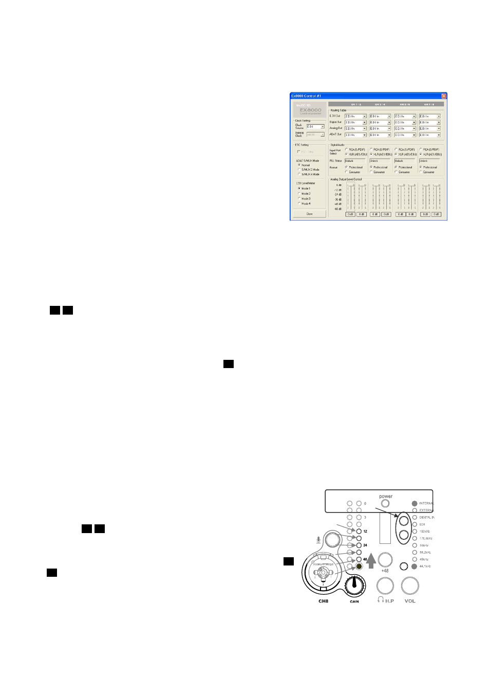
To change the audio routing when EX8000 is in standalone
mode, you need to push the two clock selection buttons (
) simultaneously. The current mode ([MODE 1] to [MODE
6]) is displayed via the output level meter display of channel
8. Please refer to the picture on the right to see which LED is
used to display which mode. A description of each different
mode follows in the next sections.
12
11
[MODE 6]
[MODE 5]
[MODE 4]
[MODE 3]
[MODE 2]
[MODE 1]
Push these buttons simultaneously
11 12