Indicators and controls – FiberPlex VIM-1032 User Manual
Page 10
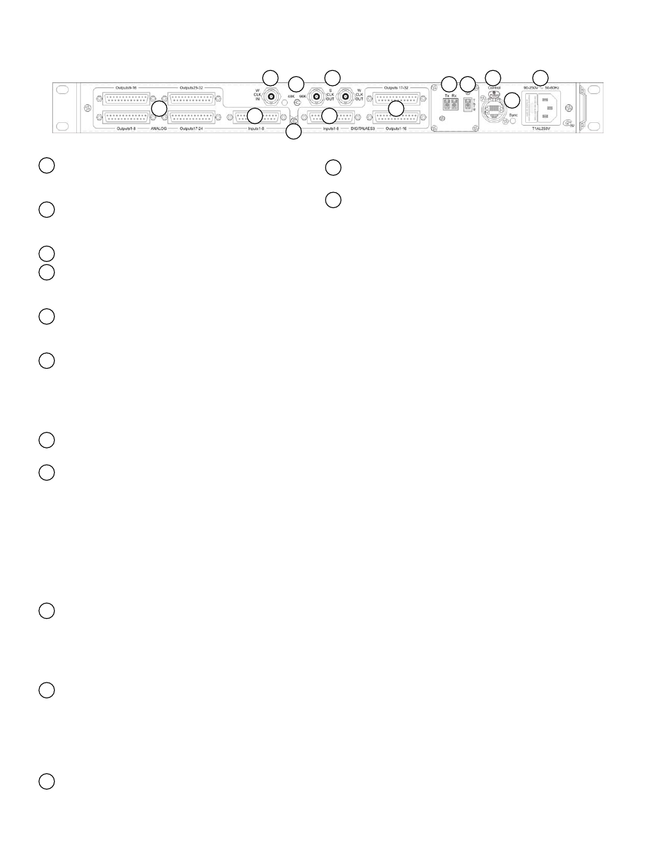
Indicators and Controls
Analog Outputs
The (8) analog line level outputs on the VIM‐1808 are connected
via (1) DB25 connectors, (8) channels per DB25 connector.
Analog Inputs
The (8) inputs are connected via a single DB25 connector. Inputs
are line level.
Input Selection Switch
Digital Inputs
The (8) digital returns are connected via a single DB25 connector.
Digital inputs are all AES3 compliant.
Digital Outputs
The (8) AES digital outputs on the VIM‐1832 are connected via (1)
DB25 connectors, (8) channels per DB25 connector.
Primary Fiber Connection
The VIM‐1808 contains a single primary pair of fiber connectors.
Always be certain to use appropriate fiber and connectors.
LightViper systems use multimode fiber. Single mode optics are
available on a custom basis for situations where single mode fiber
may already exist.
Fiber Thru Connection
Control Circuit Connector
This RJ45 connector provides (3) bi‐directional CMOS or TTL data
lines (up to 38.4KHz from VIM‐0808 to VIM‐1808 and 2MHz from
VIM‐1808 to VIM‐0808) plus voltage and GND. This connector is
used in conjunction with DGL‐422 cables for transporting Yamaha
control, or with MD3 units to transport RS‐422, RS‐232 or MIDI.
THIS IS NOT AN ETHERNET CONNECTOR – CONNECTING AN
ETHERNET DEVICE TO THIS CONNECTOR COULD DAMAGE THE
DEVICE. The pin outs for this connector are detailed in the
appendix. Most CMOS or TTL functions / equipment can be
adapted to make use of this connector.
Sync LED
This LED indicates the status of the fiber‐optic link between the
VIM‐1808 and VIM‐0808. It has three states; SOLID RED indicates
there is no sync present; ALTERNATING RED & GREEN indicates
the unit is searching for sync; SOLID GREEN indicates sync is
present (optical link) and OFF indicates no power.
Power Connector / Fuse
The AC power connection to the VIM‐1808 & VIM‐0808 are made
via the supplied IEC power cords. The internal power supply can
accept 90‐260V at either 50 or 60 Hz> The power fuse is a
5x20mm, 1A Slo‐Blo. Only replace the fuse with an exact match. If
after replacement the fuse blows again, contact Fiberplex for
service.
Word Clock External Input
Clock Frequency Switch
chooses between analog line level and digital returns
Word Clock / Super Clock Output
13
12
11
10
9
8
7
6
5
4
3
2
1
1
2
3
4
5
6
7
8
9
10
11
12
13