Specifications – FiberPlex VIM-1032 User Manual
Page 14
LightViper VIM‐1832 / 1032 Specifications
Specifications
• 8 x 8 fiber optic transport system
• Cable runs over 1.25 miles with no loss
• Rugged, lightweight fiber cable
• 24 bit / 96kHz sampling (24/48k with ext. input)
• Analog line level OR AES digital input
• Simultaneous analog / AES3 digital outputs
• Heavy gauge steel construction
• Extended range and flexibility means limitless routing options
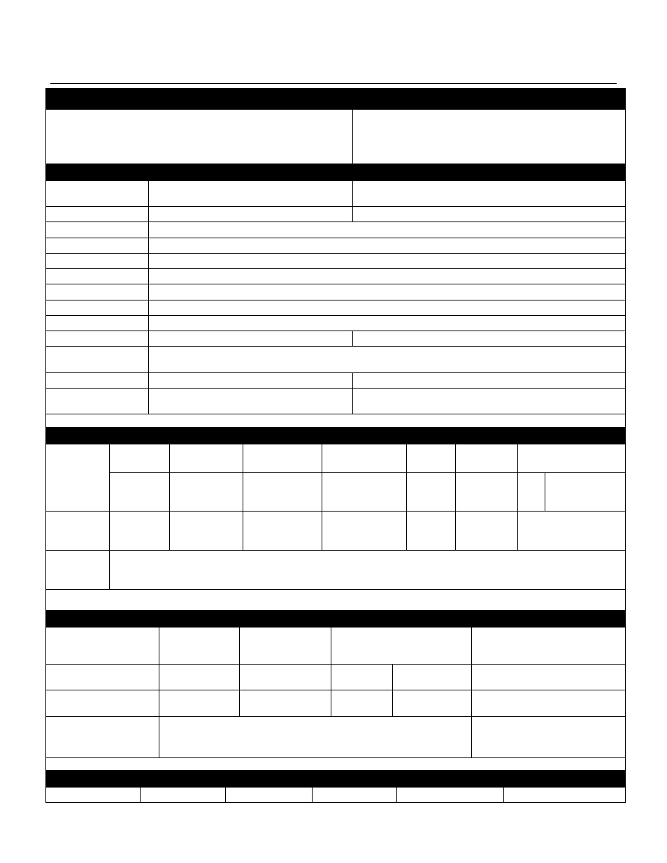
General Specifications
Total Harmonic
Distortion + Noise*1
Less than 0.01%
1 KHz @ +4 dBu
Frequency Response
± 0.5 dB
20‐20kHz @ +16 dBu
Dynamic Range
102 dB
Crosstalk
5 dB above noise floor
Sampling Rate
24 bit / 96kHz or 24 bit / 48 kHz
Latency
630
s one way, analog input to digital output, 20s one way, digital input to digital output.
Operating Temp
0 to +50°C ambient temperature.
Sync LED
LED (green) indicates optical link OK, LED (red) indicates problem with optical link, LED (off) indicates no power.
AC Power
Universal 90‐250 VAC, 50/60 Hz, IEC connector with fuse
Max Current Rating
VIM‐1808 / VIM‐0808
0.473 mA @ 90V
On / Off Control Date +
MIDI
RJ‐45 connector for logic level control, CMOS or TTL at 2 MHz max per channel.
Dimensions
VIM‐1808 / VIM‐0808
1 Rack Unit X 6.5" Deep
Weight
VIM‐1808 / VIM‐0808
300 ft Fiber Cable (tactical)
6.5 lbs
6 lbs
*1‐Hum & Noise are measured with an AES17 compliant filter at 20 kHz. Temperature condition @+10 ‐ +25° C.
Input Characteristics
Connection
Gain Setting
Voltage Gain*2
Sensitivity*3
S/N ref +0dBu
Overload
Clipping
Input Impedance
Analog Sends
1‐8*4
0
0(0 dB)
1.65 Vrms
‐83 dBu
+16 dBu
+19 dBu
XLR
TRS
1.8 K
10 K
Analog
Returns 1‐8
n/a
0(0 dB)
1.65 mVrms
‐83 dBu
+16 dBu
+19 dBu
2 K
Digital sends
& Returns 1‐8
(Mixer End)
AES3 Digital
*1–Hum & Noise are measured with an AES17 compliant filter at 20 kHz. Temperature condition @+10 ‐ +25° C. *2–0dBu is referenced to 0.775Vrms. *3–Sensitivity is the lowest level that will produce an
output of +4dBu (1.23V).
Output Characteristics
Connection
Actual Source
Impedance
For Use With Nominal
Output Level*2
Nominal Max
Before Clip
Connector*1
Analog Returns 1‐8 (Stage)
Box)*1
150
600
Lines
+4 dBu (1.23
V)
+19 dBu (7 V)
DB‐25, Tascam™ DA‐88 pinout, 8
Analog Sends 1‐8 (Mixer)
End)
150
600
Lines
+4 dBu (1.23
V)
+19 dBu (7 V)
DB‐25, Tascam™ DA‐88 pinout, 8
channels per connector
Digital Sends & Returns 1‐8
AES3 Digital
DB‐25, 8 channels per connector
*1–All XLR connectors are balanced. *2–0 dBu is referenced to 0.775 Vrms.
Optical Characteristics
Connector*1
Installation Tension
Operating Tension
Min Bend Radius
Crush Resistance
Weight