Tac‐4 installation instructions – FiberPlex VIM-1032 User Manual
Page 17
15
TAC‐4 Installation Instructions
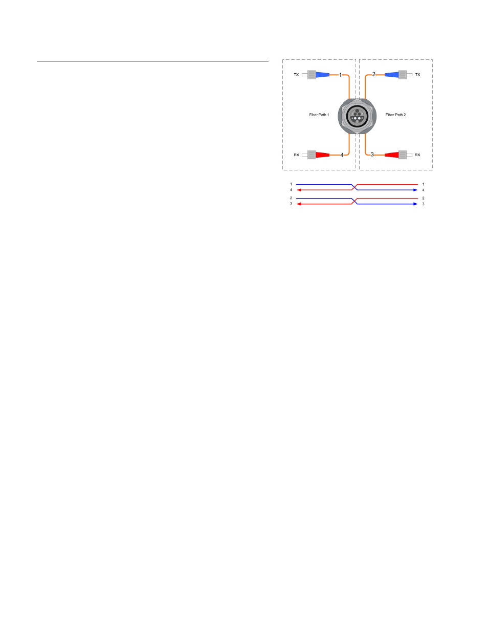
When using TAC‐4 panel mount connectors:
Due to the hermaphroditic nature of the TAC‐4 connector, channels 1 & 4 and
2 & 3 are crossed by necessity. Therefore, pins 1 & 2 should always be
connected to connectors marked TX and pins 3 & 4 should always be
connected to pins marked RX. Pins 1 & 4 are always paired together and pins 2
& 3 will always be paired together.
Important Note: A single TAC‐4 connector and cable contains (4) fibers and
can transport both pairs of fiber inputs/outputs of the EF‐2 on a single
connector / cable. If using Neutrik OpticalCon, two cables / connectors are
required, one for each pair, as the OpticalCon cable and connectors contain
(2) fibers. When using LC or ST fiber connectors on the chassis of the EF‐2, the
connectors are mounted on the rear of the unit. Alternatively these fiber
connectors can be mounted on the front panel of the unit.