Rear indicators/connections – FiberPlex WDM8 User Manual
Page 10
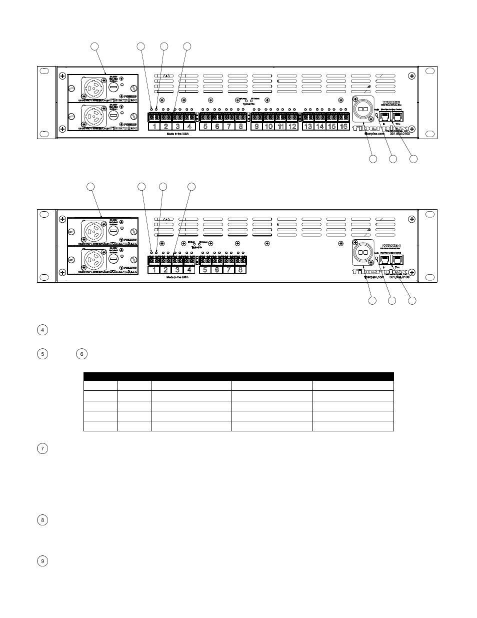
Rear Indicators/Connections
10
8
4
5
7
6
9
Figure 2 WDM16 Rear Panel (shown with optional redundant power supply)
4
5
7
10
8
6
9
Figure 3 WDM8A Rear Panel (shown with optional redundant power supply)
Power Supply Slots – At least one PSMAC must be installed in a slot for the unit to operate. The top slot is designated PS1 and the
bottom slot is PS2. For full redundancy, power supplies can be installed in both slots. These slots support ‘hot swapping’ of the supplies.
TX Fault
RX Detect – There is one pair of these LED indicators associated with each SFP slot on the unit. They correspond to the slot
directly below. Color indications can be interpreted using the following table:
TX Fault
RX Detect
SFP Installed
Transmitter Functioning*
Receive Signal Present*
Off
Off
No
n/a
n/a
Red
Red
Yes
No
No
Red
Green
Yes
No
Yes
Green
Red
Yes
Yes
No
Green
Green
Yes
Yes
Yes
*Note that some copper Ethernet and Video SFPs may have custom TX Fault and RX Detect implementations. See SFP documentation of individual SFP for more information.
SFP Slot – Install SFPs in this slot. These slots conform to the SFP MSA (INF‐8074i more information later in this manual). They are fixed
bi‐directional ports and cannot support dual TX or dual RX SFPs. Any standard MSA complaint SFP can be used in these slots including
but not limited to optical modules with data rates in the range of 155Mbps to 3.0Gbps, Ethernet copper modules, video copper
modules, copper quadrax SFP to SFP cables, etc.
Each channel is independent and will accept any format and any MSA compliant user supplied SFP module that is appropriate for the
user’s equipment. Above 500 Mbps, ultra‐low jitter SFP’s are recommended (40 psec.) as well as ITU‐T G.652.D/IEC 60793‐2‐50.B1.3
compliant fiber optic cable.
Aggregate Fiber Connection – A Neutrik™ opticalCON DUO connector provides a bi‐directional singlemode fiber interface to the
aggregated I/O of the CWDM. This optical signal carries the data using all 16(8) wavelengths internally allocated to the 16(8) external
SFP cages. This optical signal is not compatible with single wavelength passive or active optical devices. The opticalCON DUO provides
for both a tactical connections using a mating opticalCON DUO cable or a standard connection with LC terminations.
Health – This indicator serves the same function as the Health indicator on the front panel except it does not report the yellow
condition.