FiberPlex WDM8 User Manual
Page 12
Power Requirements & PSM Mounting
The power supply modules (PSMAC) accept voltages from 100‐240 VAC, 50/60 Hz. Maximum power consumption is 100W per module.
Although the power supply modules are designed to be hot swappable, it is optimal practice to insert a module into the chassis prior to the
application of AC power.
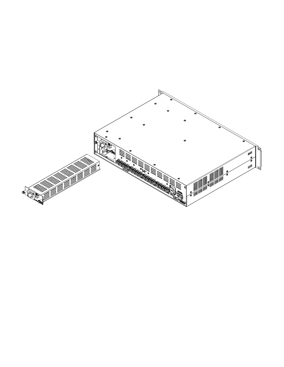
The power supplies must be installed in the top most slot when viewing the insertion end of
the respective model chassis. A secondary redundant power supply may be installed in the bottom slot.
To access the fuses, disconnect power cord, and remove the power supply unit from the chassis. Replacement fuses must have the required
current rating and must be of the specified type. Use of repaired fuses and/or bypass of the fuse holders is not recommended and will void
the warranty.
The system power requirement for a 17‐unit (maximum) rack configuration is 115 VAC @ 15 Amps; if supplied with 230 VAC, 8 Amps is
required.
Figure 5 Inserting Power Supply
Using Redundant Power Supplies
The WDM16/8 units come standard with a single PSMAC power supply installed. This configuration may be perfectly acceptable for many
applications. In the case of mission critical applications which have zero tolerance for downtime, it is advisable to add a second optional
PSMAC power supply for complete redundancy. The second supply can be inserted at any time in the unused power supply slot. Insert the
supply first, then apply external AC power.
The PSMAC and the WDM16/8 support ‘hot swapping’ of the power supplies. This means that either supply can be removed or inserted
without powering down the unit. With two supplies installed, in the event of a failure of one PSMAC, the unit will continue to operate on the
remaining supply. A new replacement can be installed and powered up without disturbing the unit.
Best practice for utilizing redundant power is to connect each supply to a different power source or ‘phase’ of power. This way if one phase
of power suffers an outage, the unit will continue to work on the remaining phase.
Power Supply Module Fuse Replacement
The power supply modules are each protected by a single 2A time‐delay fuse (Littlefuse model 218.002 Slo‐Blo). Replacement of the fuse
requires the power cord to be disconnected from the power supply AC inlet and the power supply to be removed from the chassis. To access
the fuse, use an appropriate sized flat head screwdriver and remove the Fuse Compartment Cap. The fuse will simply slide out of the Fuse
Compartment with the cap removed. Slide a new fuse which meets the stated specifications into the Fuse Compartment and replace the cap.
You may now re‐insert the power supply into the chassis and reconnect the power cord to the power supply AC inlet connector.
Replace only with identical or equivalent time‐delay fuse.