Other considerations – FiberPlex WDM8 User Manual
Page 17
Other Considerations
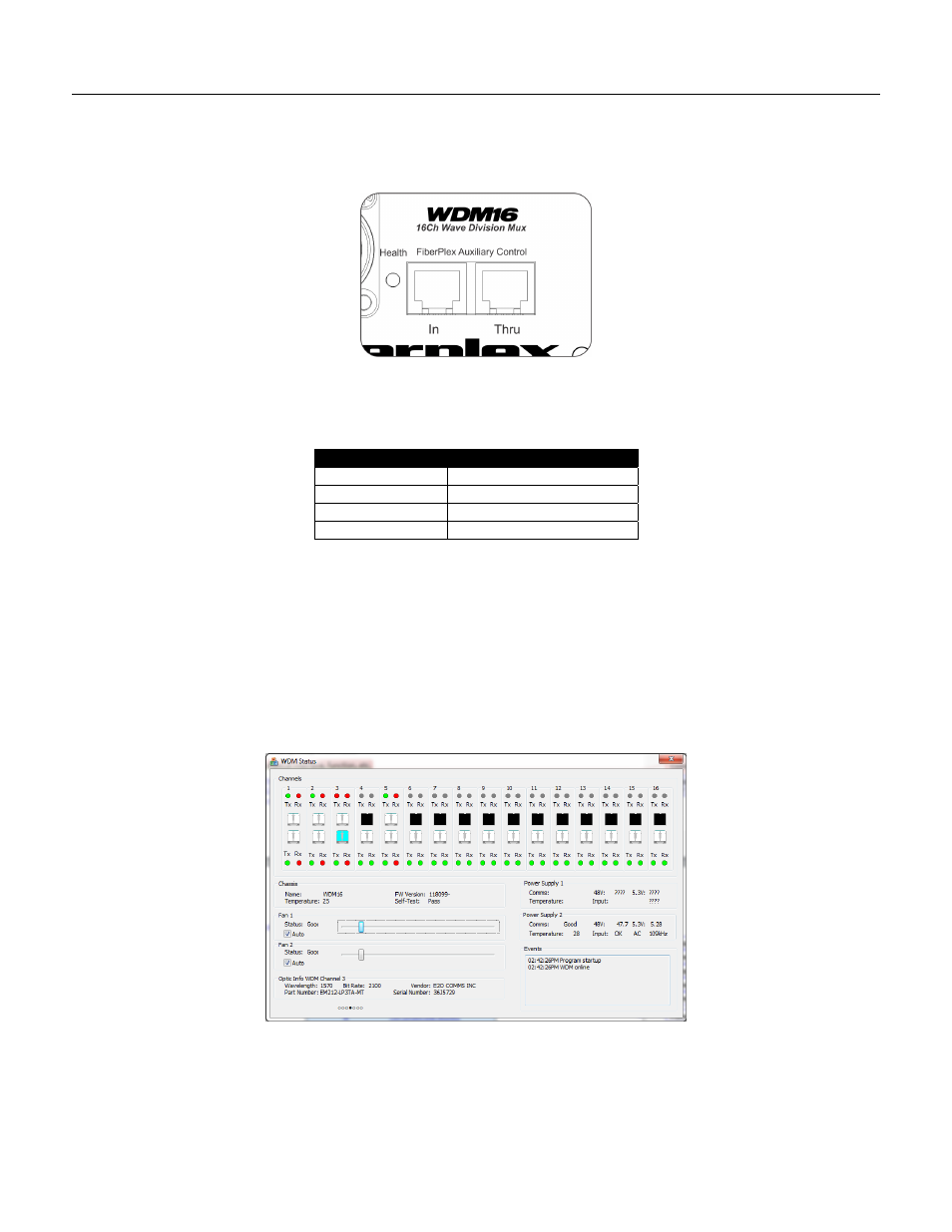
FiberPlex Auxiliary Control (FAC) Interface
On the rear of the unit, near the opticalCON DUO connector, are two RJ‐11 jacks, one marked “In” and the other, “Thru.” These support a
proprietary, 115.2 kBaud RS‐422 serial protocol that enables a controlling device to poll the status of connected devices. Up to 255 units can
be daisy‐chained on one link, with the “In” as the upstream link (eventually leading to the controller) and the “Thru” as the downstream link.
Figure 8 FAC Control on the rear of the WDM16
The pinouts of the connectors are as follows:
Connector Pin
Function
1
Rx + (to the WDM)
2
RX – (to the WDM)
3
TX – (from the WDM)
4
TX+ (from the WDM)
A standard crossover RJ11 cable can be used to daisychain units together.
For the WDM, the following information can be accessed:
Temperature of the logic board and power supplies
Channel status (SFP inserted, signal present, transmit good)
Identification of SFP models and manufacturer
Status of cooling fans, including level and operational status
Power supply Voltages, temperatures and switching frequency
An example application available from FiberPlex appears as follows:
Contact FiberPlex for more information as to availability of this and other applications.