Flowserve MJ Slurry User Manual
Page 16
MJ SLURRY USER INSTRUCTIONS ENGLISH 71569294 - 02/08
Page 16 of 42
®
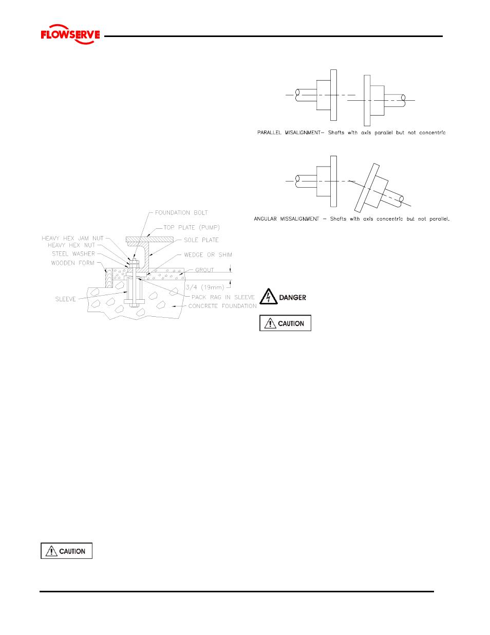
4.4 Baseplate installation
Position the pump next to the foundation and clean the
foundation surface thoroughly. Remove the rag packing
from the pipe sleeves and place wedges or ships as
close to the foundation bolts as possible. These may be
omitted if a jacking nut on the foundation anchor bolts is
preferred for levelling. Initial levelling should be within
0.75 mm (.030 inches).
Remove the flange covers and check inside the pump
nozzles for cleanliness. Kerosene is recommended as
the best solvent for removing factory applied rust
preventative. Ensure that all traces of rust preventative
are removed from the discharge and suction flange
faces, the exposed shafting and all coupling surfaces.
Flush the pump internals of any rust preventative
applied for long-term storage.
Lift the baseplate assembly, remove the shipping skids
and clean the underside of the baseplate. Position the
baseplate over the foundation and lower the unit over
the foundation bolts and onto the wedges, shims or
jacking nuts.
With the aid of a machinist's level, adjust the wedges,
shims or jacking nuts to level the pump and driver
mounting pads in each direction. Check to ensure that
the suction and discharge flanges are plumb, level, and
at the correct elevation. It is normal practice to set the
mounting pads slightly low in order to permit lowering of
units which may be required to suit future piping or
minor changes. Place washers over the foundation
bolts and install nuts. Tighten finger tight only.
Check the impeller axial clearance and that the rotor
turns freely by hand.
Note: Grout is not poured until an initial alignment
of the pump and driver has been performed.
4.5 Initial alignment
4.5.1 Thermal expansion
The pump and motor will normally
have to be aligned at ambient temperature and
should be corrected to allow for thermal expansion at
operating temperature. In pump installations
involving high liquid temperatures, the unit should be
run at the actual operating temperature, shut down
and the alignment checked immediately.
4.5.2 Alignment methods
Ensure pump and driver are isolated
electrically and the half couplings are disconnected.
The alignment MUST be checked.
Although the pump will have been aligned at the
factory it is most likely that this alignment will have
been disturbed during transportation or handling. If
necessary, align the motor to the pump, not the pump
to the motor.
4.5.2.1 Direct Driven Units:
The importance of accurate alignment of pump and
driver shafts cannot be overemphasized.
IMPROPER ALIGNMENT IS THE PRIMARY CAUSE
OF VIBRATION PROBLEMS AND REDUCED
BEARING LIFE.
A flexible coupling is used to compensate for slight
changes in alignment that occur during normal
operation and is not used to correct for installation
errors. Install the pump and driver half couplings in
accordance with the coupling manufacturer's
instructions. Note that the coupling hub faces are not
always mounted flush with the ends of the shafts.
Place the driver on the topplate such and ensure that
motor shaft and pump shaft are spaced apart by at
least 3mm (0.12”).
The purpose of the alignment procedure is to ensure
Figure 1